This application note on Torsional Vibration has been kindly supplied by our friends Dewesoft. For further information on the Dewesoft products, contact us.
Angular Vibrations in Automotive Applications
Introduction
In this application note we talk about torsional vibration, its origins, effects and how we measure them with Dewesoft.
Torsional vibration is an angular vibration usually on a shaft along its axis of rotation.
Applications
Typically occurring for example in electric motor driven systems, steam turbine plants, automotive driveshafts and generally everywhere where there are uneven rotational loads on shafts.
Torsional vibrations can have an effective range from negligible low amplitude sounds, to in severe cases broken or bent shafts. To identify and analyse this problematic frequencies we developed several modules that concentrate on machinery diagnostics. In our case we will talk about Order tracking and Torsional vibration modules.
To properly optimise a system, might it be a drive shaft, differential or a transmission we first need to analyse the designed prototype or existing production model for its flaws. With reliable and accurate data gathered from a controlled environment test. We can then redesign the unit in order to implement the changes which will reduce or completely eliminate the problematic superimposed frequencies. The newly refined part is then tested for confirmation of improvement.
We can also use this tools to determine the state of the machine as means of preventive diagnostics or to test long term reliability.
ROTATIONAL SENSORS
Rotational speed can be measured in many ways. Not all of the methods can be always used, so it’s up to us to determine the right sensors for the required job. Usually we measure rotational speed by means of:
- Tacho: A laser or optical reflection from a reflective or a stripped sticker on the shaft.
- Gear tooth: A magnetic response, induced by the hall effect sensor, from a toothed wheel, with a protruding or sunken wedge on the shaft. Sometimes a gear in the gearbox or differential can be used.
- Encoder or CDM: Encoders or CDM’s are mounted on the end of the shaft or by means of toothed belt and provide several pulses per rotation.
Dewesoft supports many different types of sensors directly and others by Event counting or Waveform timing. For example Encoder, gear tooth, tacho and CDM type sensors are mostly predefined, and you only set the input channels to sooth your type of connection. Other types of sensors have to be configured according to the pulse output they provide, so the hardware and the software knows how to interpret the signal.
Dewesoft super counters
Counters are mainly used for measuring RPM and angle of rotating machines. Dewesoft super-counters work on a 102.4 MHz internal time base, always, independent of the current sample rate. In comparison to standard counter, which only output whole numbers like 1,1,2,2,3,4, … one sample later, Dewesoft X is able to extract the accurate values like 1.37, 1.87, 2.37, … full time – and amplitude – synchronised! This is done by measuring the exact time of the rising edge of the signal with an additional counter.
EVENT COUNTING
BASIC EVENT COUNTING
Basic event counting is the mode where we can count either falling or rising edges of the signal.
GATED EVENT COUNTING
Gated event counting is a mode where the counter counts only when the gate signal is high.
UP/DOWN COUNTING
Up/down counting is a counter operation which counts up when the gate is high and counts down when a gate is low.
WAVEFORM TIMING
Period, pulse width, duty cycle and Two pulse edge separation
Period and pulse-width measurements are similar in function. The period measurement measures the time between two consecutive low to high transitions, while the pulse-width measurement measures the time that the signal is high. The duty cycle is a procedure where the ratio between the high (or low) pulse of the signal and the period is measured.
SENSORS IN TORISIONAL VIBRATION
In this category we can find: Encoders, CDM, Tachos or Gear tooth sensors. Each of them uses a different style of measurement and has different good and bad characteristics.
ENCODER AND CDM
Encoder is the most precise in terms of pulses per rotation. Normal span is from 360p / R, to 3600p / R in high end models.
They are relatively small, precise, tell the direction and have zero pulse. They require to be connected at the end of the shaft or by means of toothed belt. The problem of mounting is the main reason of why they are not used in more applications. CDM is basically the same device but lacks the zero pulse.
TACHO
Tachos are optical or magnetic sensors that usually measure one pulse per revolution (1p/R). They are used for simple rotational speed measurements because they are easy to set up and don’t require much configuration. Their disadvantage is bad precision because we don’t know what is happening to the speed during one rotation.
GEAR TOOTH AND STRIPED TAPE
It’s possible to increase the precision of Tacho type of measurement by adding reflective or inductive surfaces. This will increase the precision of measurement but at the same increase the complexity of of installation.
If we further expand the configuration by cutting one or more teeth from the sprocket, we get a zero pulse position and can now calculate the exact angle. Usually we use a 36-2 or 60-2 configuration, for good sensitivity and resolution. In case of striped tape sensors a zero pulse must be 3 pulses long. This is achieved by cutting the tape so we start and end with a black stripe and if necessary paint or cover the remaining gap.
MEASUREMENT
Measurement and analysis is done completely within Dewesoft software. This lets us combine and synchronise multiple different kinds of measurement at once. For example if the drivetrain in a car is tested, we can monitor the engine through OBD, transmission input and output with gear tooth sensors, road conditions with a camera and speed and position of the car with GPS. The software is pc based and can be run from a stationary computer, laptop or our portable SBOX data logger solution. Counters on Dewesoft Sirius hardware run with 100 Mhz which allows us acquisition of an 60-2 Gear tooth sensor at 40.000 RPM.
In our case we can use the speed provided by the counter and derive the acceleration from it. Angle in radians is calculated from Counter angle. Angular velocity in radian is calculated from rotational frequency and then derived to get angular acceleration in radians.
In Dewesoft different types of measurements are divided in Modules. Configurations and calculations dependent on the type of measurement are displayed once we open the module. In this paper we will concentrate on Modules: Order tracking and Torsional vibration.
ORDER TRACKING
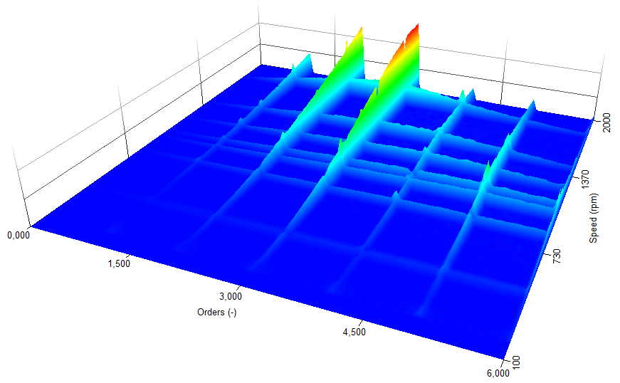
For Order tracking we need a source of signal Input and a rotational frequency source. Typically we use Vibrational acceleration or Angular acceleration for input signal and one type of encoder for rotational frequency source. In the module, we then setup the kind of measurements we want to make, be it run up, coast down or both, number of calculated harmonics, resolution etc.. If we want to control the run up/down, we can do so by using an analogue output and Function generator module.
Results are visually displayed in different 3D graph in respect to Order or FFT,
TORSIONAL VIBRATION
In Torsional vibration we measure the angular difference between two encoders, in other words twist of the shaft.
Accuracy of this measurement is greatly dependent on the accuracy of the rotational measurement. If we have sufficient pulses per revolution we can accurately see angular velocity.
ANALYSIS
As soon as we are finished with acquisition of our data, we can switch to Analyse mode. In Analyse mode we can:
- Add mathematics, filters or other signal processing functions and recalculate the results.
- View all measurements
- Print results
- Export selected data in many different formats (Excel, Matlab, Text/CSV…)
In analysis mode, it is also possible to add Math functions, and recalculate the signal to display results. It is possible to post-synchronise video files from, for example an action cam or a smartphone. The display can also be changed to sooth the needs of analysis. Results of the analysis can be printed or exported to one of many formats supported by Dewesoft.
APPLICATIONS
DRIVETRAIN MEASUREMENTS
FLYWHEEL SPEED MEASUREMENT
By measuring the timing of injector pulses we can see the fire order of the engine and compare it with the speed fluctuation of the flywell. With this measurement we see the smoothness of the engine and can determine the source of unwanted irregular angular accelerations.
If we measure during run-up we see fluctuation of RPM while the engine is under load. Order tracking further broadens the possibilities to see which frequencies grow through change of RPM.
DUAL MASS FLYWHEEL ISOLATION MEASUREMENT
Dual mass flywheel is a machine provides a constant rotating energy from a non linear source. This used to be done with a conventional flywheel, that would use the force of inertia to compensate for engines lack of power during the combustion cycles. Normal flywheel design lacks the possibility to dampen out violent torques or unwanted vibrations, but is simple in design and relatively cheap to manufacture. The dual mass flywheel is a more complex machine and thus more expensive but offers great vibrational damping.
Selecting the right flywheel for the drivetrain is therefore extremely important. It must be matched to engine and the drivetrain for optimal effect.
For analysis of performance a measurement in real conditions must be done. The measuring equipment consists of two counter inputs with two rpm sensors, 4 current sensors connected to Low voltage inputs and one CAN input for engine monitoring. RPM sensors are located on the primary and secondary side of the DMF. Rotational speed is measured on gear tooth wheels that usually have 100+ teeth with 2 or more missing for zero reference. The angular acceleration of each side is calculated from the rotational speed and inputed in Order tracking (Figure 20 & 21) to calculate and isolate the 2nd order of both sides (Figure 22).
From this two orders the isolation between primary and secondary side of the DMF can be calculated (Figure 23) and analysed to see the flywheels damping efficiency. Current sensors are each connected to an injector so that we can compare the time of fuel injection to the change of angular acceleration on the primary side of DMF. Measurements are taken in 2nd, 3rd, and if possible 4th gear to determine the characteristics trough different loads.
Expansion of the system is also possible. By using the gear position information from CAN, defining some triggers and programming a short sequencer, we could make a setup that would trigger a measurement if the car was in desired gear and at right rpm. With that a single test engineer could safely perform the measurement while driving the car.
TORSIONAL VIBRATION CONCLUSIONS
In conclusion,torsional vibrations could potentially harm the drivetrain or at least worsen the comfort and driving experience of the car. It can improve the overall quality and comfort of not only cars but all engine powered vehicles.
Finally, Dewesoft hardware and software is a good example of an adoptable system that can be used for a number of different measurements in perfect synchronisation.