What is CAN-MD?
It is a highly configurable CAN-Bus based sensors with integral DSP Microprocessor Sensing Platform used for machinery diagnostics.
CAN-MD Vibration Sensors
Firstly, vibration sensors produce large volumes of dynamic data. However, processing this data from various nodes in a bused environment has not always been possible. This is due to the limitation of bus processing speeds. Before CAN-MD, the vibration sensors gathering data on machinery diagnostic functions was all analogue and had not transitioned to digital bus communication. CAN-MD have solved this issue. All digital with high level broadband vibration data processed at the source.
Secondly, by going digital the wiring has reduced to one primary cable. The user-configurable firmware in the CAN-Med platform optimises each individual monitoring location for the best results. The CAN-MD platform can coexist and operate within a variety of CAN protocols. Bridges can converts other bus protocols such as Ethernet, RS232/RS485 and ARINC.
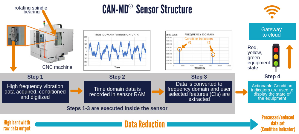
The image below provides a good description of the CAN-MD Sensor Structure.

SYSTEM DESCRIPTION OF CAN-MD
Condition Indicators (CI’s) are processed features from resident algorithms from each sensor. Therefore, CAN-MD accelerometers post Condition Indicators on the bus automatically and/or when instructed (this can be manually).
Working Principle CAN is a broadcast type bus. A message transmitted by one line replaceable unit (LRU) is received by all LRUs connected to the bus. Each LRU contains a filter to accept the message relevant to it. A data message is sent as a frame. In each frame the message is labelled by an identifier unique to the network and includes the Node ID and sensor serial number.
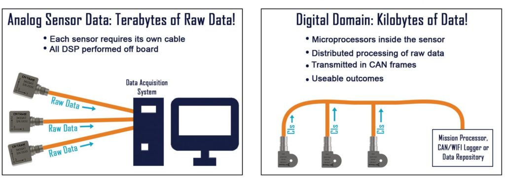
All LRU’s receive the message. Each scans the message to see if is relevant to that LRU using serial number and ID details. Data verification is easily accomplished via visual inspection of the sensor location ensure the serial number matches the data. The image below illustrates how data was processed before CAN-MD And After CAN-MD

DATA AND CONDITION INDICATORS
A Condition Indicator (CI) is the result of the onboard DSP and algorithm processing functions performed by CAN-MD Sensors. So the CI’s are provided as outputs on the CAN bus and are the primary bits of information sent to dashboards (locally or on the cloud). Therefore, the condition indicators to highlight developing faults, predicts failures or to signal “normal, warning, shut down, alarm, green, yellow, red” or other operating conditions as selected.
CAN-MD Sensors start collection processing CI’s as soon as they are turned on. The CI’s can be filtered with additional information to classify “operating mode” dependent results. CAN-MD Sensor can respond to commands over the data bus. These commands may be an order to collect synchronous or asynchronous measurements and output processed or raw data onto the CAN bus. Sensor data can be stored in a data logger through a simple user interface. Raw data is not typically stored. However, it is useful in debugging or analysing difficult vibration problems and setting up associated CI’s in the future.
CAN-MD distributes data processing across the entire network rather than one central processor. Reduces the single point failure. Each sensor has its own address and setup configuration is stored at sensor level rather than central level. By default, firmware on each sensor is physically partitioned so changes are made locally down at the sensor – simplifying validation and verification of firmware updates. CAN-MD can augment the system with additional channels without having to force a LRU change or system redesign.
To find out about the CAN-MD products, click here.


