This information on the Analysis of PCB Failure has been kindly supplied by our valued supplier, Huntron. For more information on the Huntron range, contact us.
The information on this page presents an analysis of a PCB when using a Huntron Tracker System for trouble shooting to the component level. When analysing signatures sampled from bad PCBs it is important to note “What is not there” as well as “What is there”. This can tell you alot about the nature of the actual failure.
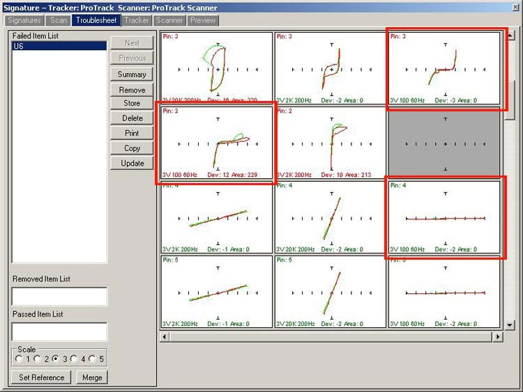
In this analysis, the customer provided two boards. One Good Example and One Bad Example of the same type and revision. A test for the Top side of the PCB was developed in Huntron Workstation for a Huntron ProTrack using a Huntron Access Prober. Signatures from the known Good PCB were stored as a test reference. It was used as the comparison when the test was run on the Bad PCB. See the image below as it shows the Troublesheet (error of log signatures). From the Huntron Workstation displaying signatures from the device U6. The reference (stored/good) signatures are shown in green. The Signatures from the bad board overlaid in red.
Signature Analysis & Inspection Images
The key signatures are highlighted in red boxes. Note that the red signatures are very much the same. Where the green signatures for those same pins are different from each other. The only way these signature differences are possible is by a very low resistance short circuit connecting the pins together. Pin 4 normally indicates a resistive signature (the angled signature in green; very likely caused by a connected pull down resistor). Where as the red signature indicated that normally connected resistance is being bypassed. In Signature Analysis troubleshooting, any resistive change is worth investigating.
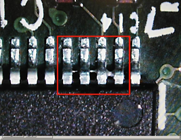
Further analysis of PCB Failure with a high powered video camera of the suspect pins (see image below) verified the actual problem of pins shorted together by solder. This appears to be a production process error.
The purpose of this test was to prove concept and usefulness of Signature Analysis as a troubleshooting tool. The analysis test was completed manually in Huntron Workstation. In addition, the test ranges used were: 3V, 100ohm, 60Hz; 3V, 2Kohm, 200Hz; 3V, 20Kohm, 200Hz.
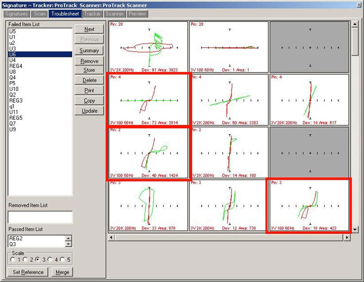
The troublesheet from this TOP side only test had components that had signature differences. These failures were caused by signature instability. Further refinement of the test ranges would reduce the Troublesheet to fewer components. The signatures from pins 2, 3 and 4 on U6 were caused by a real failure and not signature instability (unlike pin 28).
Further Analysis
The solder shorts from U6 were removed and the component retested with the Huntron ProTrack and Access Prober. Finally, the resulting signatures for the test are displayed below.