This application note on Remote Motor Monitoring was supplied by our supplier Acromag.
Motors are used in many automation applications. To prevent unexpected failures, many motors have built in thermal overloads. Also, some companies add vibration sensors to alert them when a motor is not behaving properly. However, many organisations are not aware there is another simple motor monitoring option to indicate when service is required.
With current sensing transducers and Ethernet I/O modules, you can easily Remote Motor Monitoring over the Ethernet from anywhere in your operation.
As motor bearings begin to wear, the motor must work harder and there is a measurable increase in current draw to the motor. This higher current draw is an early warning that an impending failure of the motor is about to occur. By installing a current sensing transducer on any of the wires that supply power to the motor and interfacing the measurements to your control system, you can identify a motor under stress before it becomes a problem.
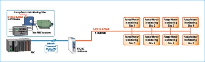
Often, the process controller is not located near the motors. In this case, you can connect the analogue output (4-20mA or 0-10V DC) from current sensing transducers at the motors to Acromag’s BusWorks®
- XT Ethernet I/O Modules. The I/O modules are ideal for interfacing collected sensor data to a remote Programmable Logic Controller (PLC), computer or SCADA system across a distributed network.
- BusWorks XT1210 models can interface eight current inputs while the XT1220 models offer eight voltage inputs. I/O modules convert the sensor’s analogue output signals to digital data for Ethernet messaging to the control system. They support Modbus/TCP, Ethernet/IP or Profinet communication protocols.
System controllers can retrieve the data from the remote I/O modules across long-distance networks or from hazardous locations for continuous monitoring of the motor’s current draw. The I/O modules act as slave units ready for polling by a network master. Alternatively, peer-to-peer communication between two I/O modules can also be used to reproduce the analogue signals over any Ethernet media (copper, fibre, wireless) without a controller for interfacing to a remote display, recorder, or other instrumentation.
A PLC or networked computer can create an initial profile of the motor’s current draw under load. The maximum current draw level establishes the upper control limit. Using this upper limit, the control software is programmable to issue alerts if the motor current draw exceeds the upper limit for a sustained period. The alert can serve as an early warning for preventive maintenance action to ensure the process served by the motor continues to operate.
If an alert identifies the motor requires servicing such as a bearing repack or replacement, the maintenance can then be scheduled at a convenient time to minimise process interruptions and greatly reduce service costs. Without current draw monitoring, the motor could fail unexpectedly at the least opportune time and at great costs.
Monitoring motor performance is especially important for a process that operates 24/7. Under these circumstances, unplanned maintenance costs would include lost production plus collateral consequences. Loss of raw material, damage to related equipment, and expedited repair fees may all be incurred when the motor fails unexpectedly.
Acromag and NK Technologies have partnered to provide a networkable solution for monitoring multiple motors used in a manufacturing process or any other operation. NK Technologies designs and manufactures current sensing transducers that work seamlessly with several I/O device options that Acromag offers. This allows companies to effectively and efficiently keep an eye on the motors that are required to keep their process up and running.
Please contact us for more information on the Acromag products used for this Remote Motor Monitoring application.