Data acquisition guru at Dewesoft, Grant Maloy Smith has provided the best definition an Inertial Navigation System. Click here to read his original blog. Grant has a way of breaking things down component by component and relating back to examples that everyone is familiar with.
In this article you will learn about what is an Inertial Measurement Unit also known as an IMU and an Inertial Navigation System aka INS. You will see what inertial systems are and what they can do, how they work and where they are used.
So, let’s start!
What is an Inertial Measurement Unit or IMU?
IMU is an Inertial Measuring Unit. It’s the sensors such as gyroscopes and accelerometers that measure the angular position and displacement of an object in three-dimensional space.
What is an Inertial Navigation System or INS?
INS is the Inertial Navigation System. It includes the IMU sensors from above. Plus it includes a sensor for receiving position data from GNSS satellites in space. It also may include magnetometers for measuring magnetic fields in three-dimensional space.
INS often includes advanced data processing such as Kalman filtering. Referencing a known starting position, it uses the outputs from the IMU to determine the real time position and course of an object.
The object can be a car, a submarine, plane or any machine that operates in three-dimensional space.

So, why do we need Inertial Navigation Systems?
Basically, we need INS to allow us to navigate from point A to point B.
Just about every car, plane, ship, submarine and smart phone has some kind of navigation system. You location is shown on a map based on triangulated position data from GPS/GNSS satellites in space. Or in the case of the smart phone, data from mobile phone towers at fixed locations.
However, what happens if there is no access to satellites or mobile phone towers?
So how does a submarine navigate once it submerges? There is no GPS under water! So how does the submarine crew know where they are going? Or how fast? Or their exact position? INS Systems are the answer.
An INS uses precise accelerometers, gyroscopes, and magnetometers with advanced processing. This allows it to calculate an object’s position relative to the known starting point, speed, and direction. Once the submarine’s INS is calibrated to a known reference point, it can “dead reckon” accurately from that point forward.
Dead Reckoning is a system that uses a known starting position. It then adds the IMU/INS data to that position in order come up with the object’s current position and course. However, no INS is perfect. So, inaccuracies will occur – especially the longer the system is “dead reckoning”.
Modern military submarines are equipped with incredible accurate, low drift INS modules. So, when satellites and other external references become available the system is recalibrated, eliminating any errors that accumulated.
INS is used by commercial and military aircraft, spacecraft, missiles, drones, robots and integrated into many mobile phones and video game controllers.

So generally, Inertial navigation is used as a fall-back system that can dead reckon when GPS/GNSS navigation is not available. For submarines and spacecraft, it is their primary method of navigation. Aircraft and other vehicles use INS in close conjunction with GPS/GNSS and other absolute position references.
The importance of IMU
Inside every INS – is the all-important IMU. IMU is a sensor package. It contains at least three orthogonal gyroscopes and three orthogonal accelerometers. Sometimes there also three magnetometers that measure magnetic dipole moments or magnetic fields.
IMUs are used to measure the objects:
- Angular rate – rate at which an object is rotating around its axis
- Specific force – difference between absolute acceleration and gravitational acceleration
- Orientation – object’s position in three-dimensional space
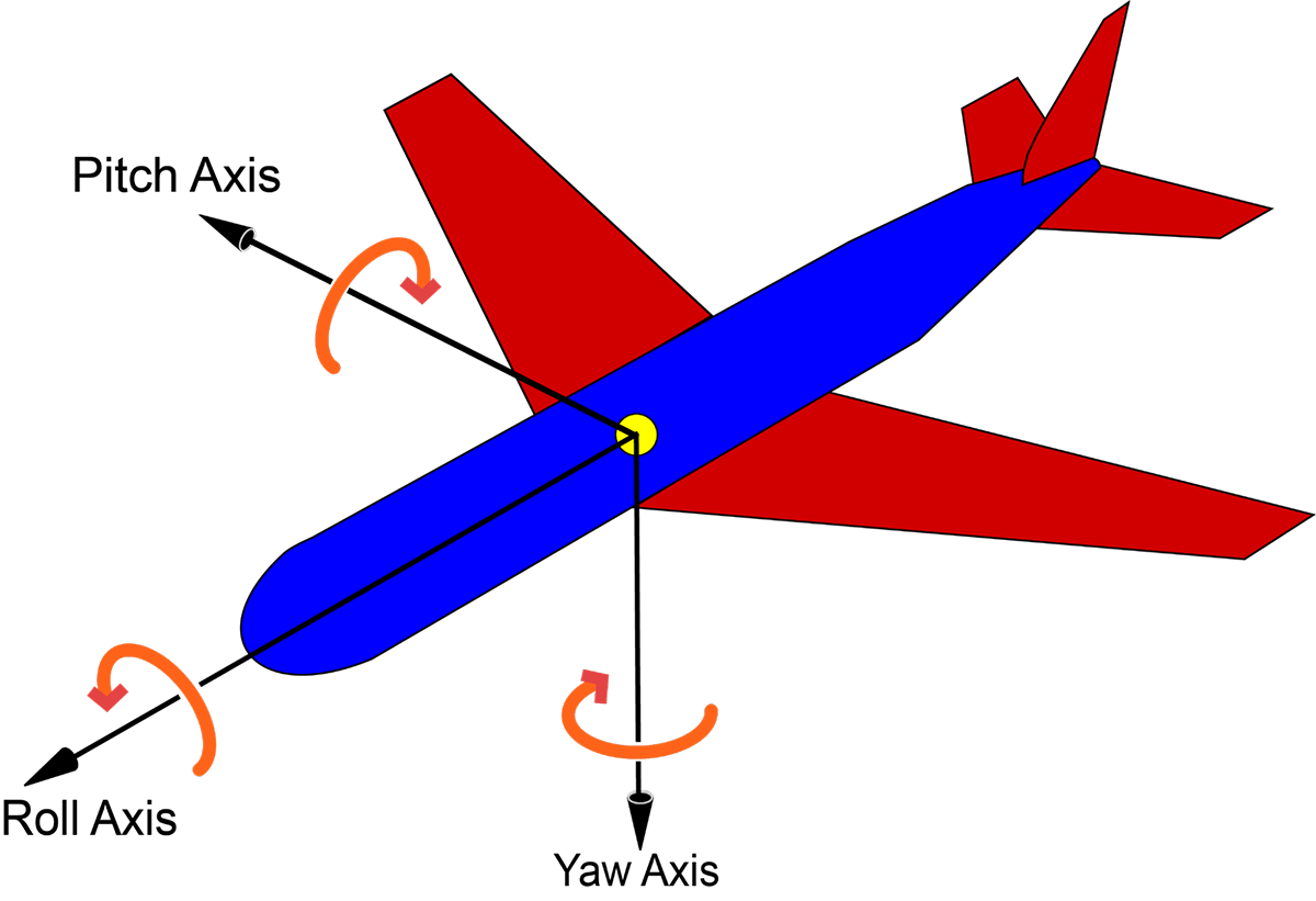
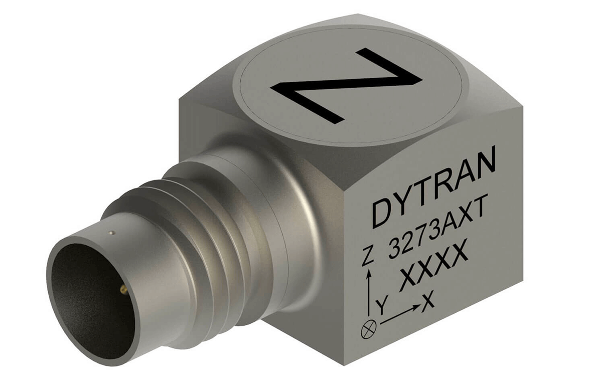
Each of the three main axes – X, Y and Z (also known as roll, pitch and yaw) have at least one accelerometer, one gyroscope and usually one magnetometer.
Why do we need 3 sets of sensors?
A single inertial sensor can only measure along a single axis. However, we move in three-dimensional space. Therefore, we mount three inertial sensors together in an orthogonal cluster. A 6-axis system consists of 3 x accelerometers and 3 x gyroscopes. When we need magnetic fields for navigational purposes. We add a magnetometer along each axis = nine sensors.
Therefore, an IMU measures raw angular velocity of the object it is connect to. It also measures the specific force/acceleration and magnetic fields.
So, when we added advanced signal processing and data filtering, such as Kalman filtering, the IMU becomes part of a larger system called an INS or inertial navigation system. When it is used for navigation, the INS can be referred to as an AHRS or Attitude and Heading Reference System.
What’s the difference between an IMU and an INS?
The IMU is the sensor subsystem of an INS. The INS takes the raw outputs from the IMU processes them and calculates changes in an object’s relative motion. The INS references these changes to a known starting point, speed and direction. Therefore, providing real time position and vector output.
IMU’s can be integrated into an INS. Or they can be separate pieces of hardware that connect to an INS.
The INS calculates and outputs:
- Attitude – pitch, roll and yaw centred about the objects centre of gravity
- Position, Position Velocity and Orientation – in three-dimensional space
- Linear Velocity – a vector quantity that consists of both magnitude and direction
- Angular rate – the rate at which an object rotates about its axis
Main INS Technologies
GNSS Receivers
To connect to the satellites in space a sensor is required. A GPS or GNSS sensor housed in dome like structure with an antenna inside. It must have line of sight to the sky to receive data from the GNSS constellations in space.
Gyroscopes
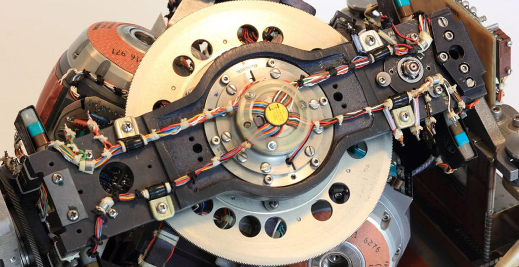
Gyroscopes are mechanical structures consisting of a spinning rotor that is free to assume any orientation. Orientation of rotor is not affected by tilting or rotation of any part of the outer frame or inner gimbals. It is still used in applications that require the most accuracy and long-term stability. Still the choice for submarines.
Since the 1960’s, smaller accurate gyroscopes have been developed. Such as the RLG- Ring Laser Gyroscopes, FOG – Fibre Optic Gyroscope, Quartz/MEMS Gyroscope.
Gyro Sensor Types by Application
Gyroscopes are grouped into four categories based on their accuracy and drift performance
- Consumer – smartphones, gaming consoles and other consumer products
- Industrial – UAV’s, drones, manufacturing processes and environments
- Smart Weapons – related military equipment
- Navigation – Aircraft, spacecraft, submarines, cars, farm and construction vehicles and land based military vehicles.
RLG, FOG and Quartz/MEMS gyros are used across the wide range of applications. RLG and FOG have replaced mechanical gyroscopes in some applications. However, Mechanical gyroscopes still provide the best long-term stability and are preferred for dead reckoning applications in submarines and some aircraft.
Accelerometers
Accelerometers are sensors. They measure a change in velocity over time. They are proof mass suspended by a spring. The longitudinal direction of the spring is the sensitivity axis.
Therefore, when a sensor is subject to a change in velocity along this axis, the proof mass will move and compress the spring. The amount of compression is proportional to acceleration. Therefore, we measure and output this value. Acceleration is measured in g or “G force”. Also known as metres per second squared.
Magnetometers
A compass is a magnetometer in the simplest sense. However, in IMU and INS Systems measure magnetic fields in more detail. Magnetometers provide a three-dimensional heading reference.
Kalman Filtering
Kalman filtering is an algorithm that essentially combines sensor data with predictive data. This is a two-stage real time linear quadratic equation. Stage one predicts and weights the accuracy of various inputs. Second Stage applies a weighted average to the inputs. This recursive process improves the accuracy of navigational outputs from GPS/GNSS systems and is integral to inertial navigation accuracy.
Inertial Applications
INS Systems applications and most centred around navigation including:
- Road vehicle navigation – cars, trucks, buses, motorcycles
- Air navigation – commercial and military aircraft
- Off road navigation – military vehicles, farm machinery, tractors etc.
- Space navigation – spacecraft and satellites
- Undersea and surface ship navigation – boats, ships and submarines
- Mining and drilling tunnels – calculating distance and direction underground
- Weapons guidance – missiles and other guided munitions
- Road vehicle testing – Advance driving assistance system of autonomous vehicles, test track testing
Dewesoft IMU and INS Solutions
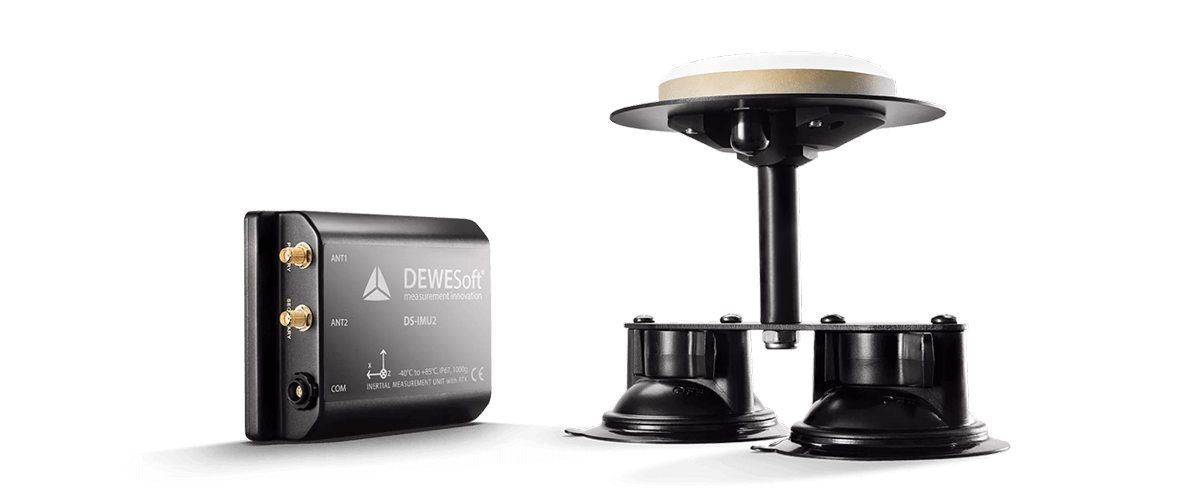
DS-IMU1
The Dewesoft DS-IMU1 is a miniature, rugged and reliable GPS aided navigation system with operations up to 100 Hz output data rate.
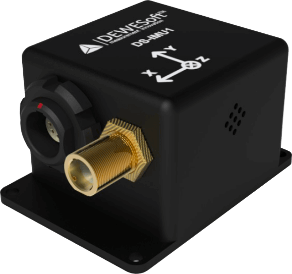
Key features:
- Combines inertial sensors together with GNSS receiver coupled in a sophisticated fusion algorithm to deliver accurate and reliable navigation and orientation
- GNSS receiver supports GPS, GLONASS, BeiDou, GALILEO, WAAS, EGNOS and GAGAN Systems
- IP67 & MIL-STD-810G environmental protection
- Up to 100Hz output data rate
- Connected over USB
- Fast & Easy to install
Navion i2
The Dewesoft NAVION i2 is a GNSS supported inertial measurement platform. It measures orientation, position, velocities and accelerations.
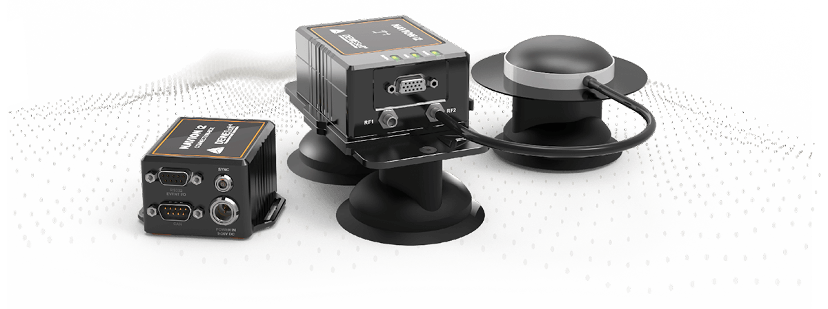
Key Features
- Ethernet based, enabling the remote connection to the system directly via DS-WiFI4
- Dual frequency GNSS receiver
- RTK with 1 cm position accuracy
- DGNSS, SBAS augmentation supported
- Dual GNSS antenna measurement for accurate static heading output
- PPS output for device synchronisation
- Fast & Easy to install
DS-GYRO1
The Dewesoft DS-GYRO1 is a miniature, ruggedised and reliable inertial navigation unit.
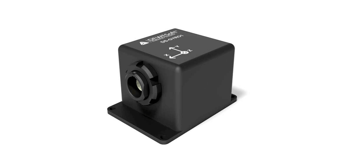
Key features:
- Combines inertial sensors in a sophisticated fusion algorithm to deliver accurate and reliable orientation
- IP67 and MIL-STD-810G environmental protection
- Up to 500 Hz output data rate
- Connects via USB
- Fast and easy to install
Third Party INS and GNSS Systems Support
Dewesoft X Software (and all Dewesoft DAQ systems) are compatible with a broad range of third party INS and IMU sensors including:
- All NMEA compatible GNSS devices (multiple manufacturers)
- Oxford OXTS inertial sensors
- Genesys ADMA inertial systems
- TopConn brand GNSS
- Novatel brand GNSS