This Data Acquisition Solutions application note has kindly been provide by our friends Dewesoft. If you would like more information on Dewesoft’s range of products, contact us.
Data Acquisition Solutions
This application note shows how DEWESoft Data Acquisition solutions can be safely and easily used with servo motors, stepper motors, etc. in conjunction with actuators, torque fixtures or other automation devices for control-type projects. The combination of DEWESoft X3 software along with an analogue output device allows the user to easily control the forcing function of the test fixture. While simultaneously measuring signals and inputs from the instrumented part. This configuration makes tasks such as File Playback possible where the user collects field data then brings the part back to a laboratory environment where the field data can be replayed and simulated for many cycles.
INTRODUCTION
In the early days of Programmable Logic Controllers (PLC’s), the technology was revolutionary, simplifying millions of projects, replacing hundreds of relays and timers per project, speeding up various processes and making once time-consuming tasks a breeze. Many universities, regardless of the program thrived on teaching students the basics to circuits along with the industries advancements in PLC’s. The degrees more specialised in their own areas of interest. With only a few degrees reaching detailed discussions and education in the topic of PLC’s.
Younger test engineers and technicians have a great deal of knowledge in many aspects of test and measurement including 3D modelling, material properties, advanced calculations, etc.; however, they lack the experience in traditional test setups such as the use of PLC’s. The industry is moving to stand alone solutions with easy and intuitive Graphical User Interfaces (GUI’s).
With the increases in demand for productivity in the test and measurement industry, more test engineers and technicians are looking to set up control projects. But would rather not go back to learning the basics and yet another software to control a traditional PLC. This application note goes through a simple way to use DEWESoft’s X3 software and Data Acquisition Solutions which many test engineers and technicians are already familiar with and apply that knowledge to perform control projects in a safe and timely manner.
HARDWARE SETUP – Data Acquisition Solution
AUTOMATION FIXTURE
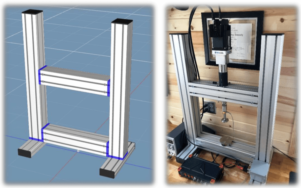
The first step to any project is designing and building a test fixture in which to perform the test. For this example, we have designed and built a small load frame out of anodised extruded aluminium to house a linear actuator and servo motor. In this example we used a Tolomatic ERD20/BNM05/SM154.2/LMI actuator along with a Tolomatic ACSI34-1Q1-B servo motor to apply our forcing function and a Futek LCM325 load cell to measure load in our part which could also be used at the feedback for PID Control.
ANALOG OUTPUT DEVICE
Any SIRIUS unit with Analogue Output (AO) and the function generator software upgrade can be to send the control signal to the servo motor. In this case we used a SIRIUSi-3xHV-1xACC+-2xACC-1xMULTI-1xSTG unit. In this test, we used the AO from the Multi-channel and used the STG-channel for the Load Cell.
DS-WDT WATCHDOG
The DS-WDT Watchdog could also be used at a safety precaution. With the SIRIUS Analogue Output, the user can look for a heartbeat from DEWESoft throughout the test. If the heartbeat is missing, the DS-WDT Watchdog can be programmed to send a digital message to the motor stopping or coasting to stop motion.
SOFTWARE SETUP
ANALOGUE INPUTS SETUP
The analogue input channels need to be configured based on the sensors used for the test. The Simple Measurement Using DEWESoft Pro training is a great resource to setting up your analog inputs.
FUNCTION GENERATOR
The function generator is an additional software package in which the user can define the analog output signal. Using your analog channel as “Signal Output” and creating either a Sine, Triangle, or Arbitrary waveform will be the most practical. The following image shows a user defined arbitrary waveform to program the actuator to perform a specific task. In the arbitrary waveform setting, old data could also be copied to simulate data that has already been collected.
Configuring the waveform, the frequency, number of cycles, and output initiation should also be set. In this case we have set our frequency in a manner where the waveform will repeat itself every 10 seconds (frequency of 0.1Hz) and will be performed for 50 cycles. We have also programmed this analog output to have a manual start once we are in measurement mode.
DS-WDT WATCHDOG
If the DS-WDT Watchdog is to be used. It will also need to be programmed.
THIRD PARTY SETUP
During the first test for a new setup, a few parameters must be programmed into the automation system. So that the system knows what to do upon startup. And how to interpret the analogue output from the SIRIUS System as well as the digital output from the DS-WDT Watchdog if the DS-WDT Watchdog is used.
“Home Position”. In this example I programmed my motor to retract to actuator until its hard-stop (at 10% load) then extend 0.5 inches.
Analogue Input. First, we select that we want to operate in Analogue Position mode. Then select that we want voltage to define position for a stroke-controlled application.
Digital Input. Finally, we select that we want one of the digital channels to “stop motion”. This selection must match how the user has wired in the digital signal. As there are 4 conductors to digital inputs in this case.
AUTOMATED MEASUREMENT
Once your hardware and software has been programmed. Go to measurement mode to begin running your automated test. If the function generator starts “manually”. The user will have to go to the control tab and select “Start Output”. Once the test in initialised, the user can watch the test perform.
CONCLUSION
Previously users have had to use multiple systems to perform the forcing function and the Data Acquisition Solutions. Or have had to make the choice between the stability of a PLC with limited options in terms of Data Acquisition and post processing; or flexibility in terms of DAQ and post processing with the susceptibility from the control aspect. By using a combination of DEWESoft’s hardware and software in conjunction with Tolomatic’s easy to use programmable motors. The user can get the stability of a PLC. But also the flexibility and GUI offered by DEWESoft’s powerful hardware/software combination.