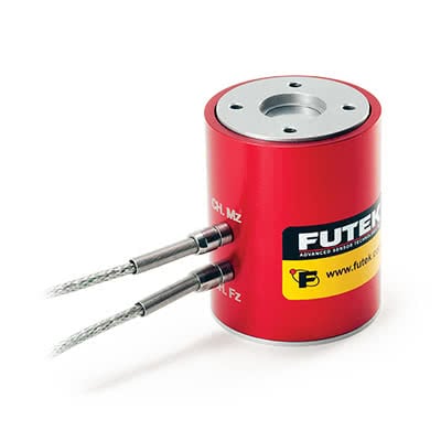
Perfect Torque Sensor Sizing Criteria for Servo Motors
At the heart of many automated assembly platforms and robots is an electric motor. If the motor is the heart, then the brain is the controller and closed loop control system.
However, the motor and controller wouldn’t be complete without sensors to provide relevant control information and complete the control loop. So, to extend the analogy, these sensors would be the nerves. One of these nerves would be a torque sensor, but just like an organ transplant, you cannot add any torque sensor to your system; the torque sensor needs to have the necessary specifications to meet your system’s needs. To preliminarily determine your sensor’s specifications, you will need to:
- Determine the maximum torque to be measured
- Determine the necessary system accuracy
- Determine Electrical Interface Requirements
Step 1: Determine the Maximum Motor Torque
When selecting a torque sensor, you must determine the maximum torque you expect the motor and/ or gear-head to produce. A common misconception is that the nominal or maximum continuous torque determines the maximum capacity, when in reality the nominal or maximum continuous torque does not take into consideration the potential for a motor to stall. Since stall torque can be several orders of magnitude greater than nominal or continuous torque. You would damage or destroy the sensor in a stall scenario if you chose the nominal maximum torque. Therefore, it is important that you size your torque sensor based on the expected stall torque to prevent damaging the sensor.
Step 2: Determine the Necessary System Accuracy
The accuracy of your torque sensor can be defined by the smallest amount of torque the sensor can reliably measure. If the minimum generated torque has not yet been determined for your system, then you can preliminarily determine your minimum torque using the torque gradient and minimum operating speed of the motor. For example, a servo motor that has a torque gradient of 0.017 mNm/RPM at 1000 RPM will have a minimum operating torque of 0.017 Nm. This value would represent the system accuracy that would be necessary for selecting the proper torque sensor.
Step 3: Determine Electrical Interface Requirements
Your DAQ or PLC has specific signal inputs it can accept so your sensor solution must be able to output those signals. For instance, some systems can handle +/- 10 VDC or 4-20 mA, while other systems can handle mV/V or SPI signals. Knowing what your system supports will allow you to select a sensor that can interface with your system.
However, if your sensor cannot produce the analogue signals your DAQ or PLC supports. You will need an amplifier to bridge the gap. (In the conceptual design we see an example of the relationship between a FUTEK TTF Torque Series sensor, FUTEK IAA Series Amplifier, and a PL/Motor Controller). The amplifier, used for full bridge sensors with mV/V signal output, will convert a mV/V signal to voltage, current, or the correct signal for your DAQ or PLC. With the requirements of your DAQ and PLC in mind. You’ll be able to select the sensor and any supporting hardware you need for your system.
You are now ready to explore torque sensor sizing options and pick the perfect one for your application. Keeping your torque maximum, minimums, and electrical requirements in mind. You’ll be able to narrow down your selection of sensors to find the sensor that fits your needs perfectly.
For further information, contact us
