This case study on “Space Telescope Vibration Measurements & Modal Analysis” was written by Helmut Behmüller, Account Manager of our partners, DEWESoft. To view the original article click, here.
Firstly, we believe it is important to share this type of content. As it highlights the forward-thinking process that Dewesoft undertakes when designing a system and developing software. Their aim is to provide system (hardware and software) that provides high precision vibration measurements for real life applications. Let’s look at how Dewesoft achieves this.
Summary of Space Telescope Vibration Measurements & Modal Analysis
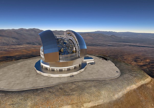
The European Southern Observatory’s (ESO) Extremely Large Telescope (ELT) is scheduled to be completed in 2027. It will be the world’s largest optical and near-infrared telescope.
As part of the construction, individual components of the telescope need to be examined. This is to assess for possible disturbances that could affect the quality of the astronomical observations.
Dewesoft’s SIRIUSie Data Acquisition System and Software was selected for the task. It provided high precision vibration measurements. As well as modal analysis of individual parts of the ELT. Therefore, providing future interference free views at the edge of a visible universe.
Introduction
Firstly, the European Southern Observatory is an organisation established in 1962 and consists of 16 European Government States. Its headquarters are in Garching, Germany. It brings together 750 staff from over 30 countries. As well as may collaborators worldwide from over 130 different countries with various technologies and data.
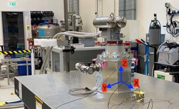
Picture 1: Measurements with cryocooler on rigid optical table
Establishing Measurement Routines
Firstly, the active ELT components that required specific measurement were identified. This consisted of pumps, fans and mirror supports.
Dewesoft implemented specific data acquisition measurement and data evaluation routines for vibration analysis. As well as modal analysis for the mirror supports. Routines were guided by ESO Engineers and technicians.
Why Dewesoft?
Dewesoft designs and manufactures versatile and easy-to-use data acquisition, test, and measurement instruments. Used in the world’s most advanced laboratories. The measurement equipment supplied for this project included:
Hardware
- 1x SIRIUSie – 8 channel isolated SIRIUS High-speed EtherCAT slice
- 1x DS-IS-20 – 20 N inertial shaker with external amplifier
- 1x DS-IS-IS-10 – 10 N inertial shaker with external amplifier
- Multi-axis accelerometers
- Impact hammer
Software
- DewesoftX – data acquisition (DAQ) software
- DEWESOFT-OPT-MODAL-TEST – Modal test option (frequency response function)
- DEWESOFT-PLUGIN-MODAL-ANALYSIS – Modal analysis plugin
- DEWESOFT-OPT-FFT-ANALYSER – Dewesoft FFT Analyzer option/frequency domain
- DEWESOFT-OPT-C++-SCRIPT – Dewesoft C++ script
- DEWESOFT-OPT-FG-MUL – Multichannel function generator
Calculations for Vibration Measurement
Firstly, calculations of the vibration behaviour were initiated by using the finite element method (FEM). This is the basis for the metrological analysis of the actual components.
For both the vibration measurements and the modal analysis, the working group first examined the respective task using a dynamic theory model. Then derived a measurement strategy. Before the actual measurements, the expected system behaviour was then simulated by structural mechanics. Based on these results, the guideline values and component tolerances were defined.
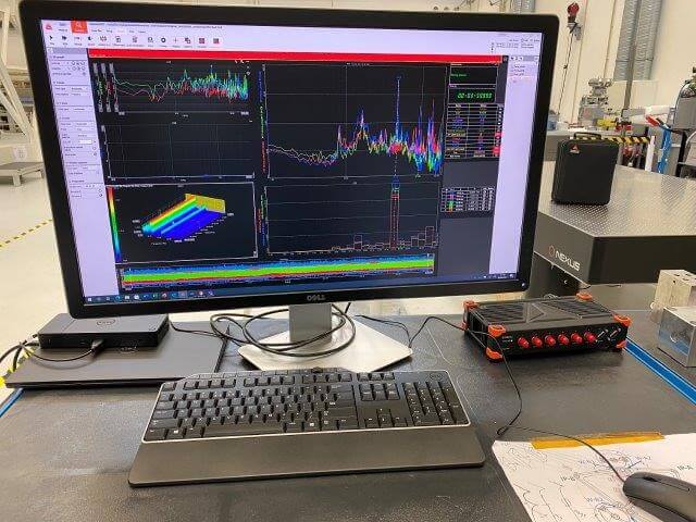
Figure 2. Laboratory setup (transfer function) at ESO for vibration measurement with the Dewesoft SIRIUS modular data acquisition system
Future Uses
In the future, the ELT will be used for top-level European research in the field of astronomy. The location is Cerro Armazones. A Mountain with a height of 3,060 metres (10,040 feet) in the Chilean Atacama Desert.
The giant telescope should help to answer many of the unsolved questions about the universe. With its primary mirror – having a diametre of 39 metres and made up of 798 hexagonal mirror elements. It can collect 13 times more light than the largest optical telescopes in existence today. It will provide images 16 times sharper than those of the Hubble Space Telescope.
From a research point of view, it will support studies of a wide range of topics from basic physics to cosmology. The telescope will observe our solar system. As well as extrasolar planets, nearby galaxies, or distant observable objects at the fringes of the visible universe.
As a modern high-performance telescope, it observes space in the visible and infrared frequency spectrum. However, movements of the telescopes components of even a few nanometres can have a major impact on the observation and image quality. Therefore, very high-quality demands are placed on the ELT mechanics and components.
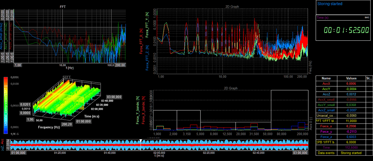
Figure 3. A typical evaluation of the measured vibration data with the Dewesoft X Software
Preventive Analysis to Avoid Disruptions
The background for the early testing is because in large telescopes, the number of critical components could lead to a reduction in performance. Due to possible malfunction is very high. In addition, special tests once it is installed often cannot be carried out. This is due to the complexity of the system.
After all, subsequent corrections would lead to enormous delays in commissioning. Simply because of the number of components. The Dewesoft measurement technology makes it possible to check potential disturbance variables. Including their causes and effects on prototypes or end products throughout the project. Also before the components are assembled in the ELT.
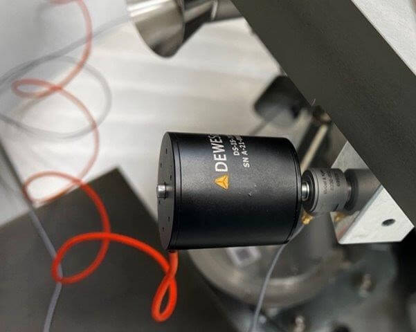
Figure 4. The kinematic mirror supports are excited with a DS-IS-20 inertial shaker – which allows both the location and the direction of the force excitation signals to be varied.
Vibration Measurement: Introduced Forces Recorded Indirectly
Active components such as pumps or fans can cause dynamic forces. These trigger oscillations and vibrations in the entire system and impair the observation quality of the ELT. Therefore, to measure these forces, Dewesoft has developed and set up corresponding test arrangements with precisely defined boundary conditions. The forces are measured according to the principle of gravitational mass.
For this test, the engineers and technicians mounted the test system. Including any elements intended for damping. Onto a heavy optical table with known dynamic properties in terms of mass, stiffness, and deformation modes. Coupling vibrations between the test object and the table were minimised. This was due to the heavyweight table. Which was kept suspended by controlled air springs and kept the test system decoupled from floor vibrations.
In this test procedure, forces lead to an acceleration of the table. This acceleration was recorded and specifically measured. Allowing the measurement software to calculate the forces introduced. Therefore, vibration measurement points at the component level make it possible to identify any improvements needed at an early stage. And not when all components are installed in the overall system. As it would be difficult to access for measurements and correction work.
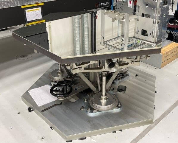
Figure 5. The main mirror of the ELT consists of 798 precise hexagonal reflecting elements.
Modal Analysis: Simple and Efficient Quality Check
Each of the 798 hexagonal mirror elements that make up the ELT’s large primary mirror is mounted on so-called kinematic mirror supports. These are used to lift and adjust the very rigid elements.
Firstly, the behaviour of this mechanism had to be described and characterised dynamically using modal analysis (excitation by vibration shaker or impact hammer).
Secondly, the calculated and simulated behaviour during excitation is compared with the actual measured modal response. This allows conclusions to be drawn about assembly errors or damage. Such as being due to structural vibration to structural parts. Even before the mirror elements are even assembled. When the telescope goes into operation such errors could affect observations.
So, to create stable boundary conditions for the modal analysis and the determination of solid motions of the mirror, a very stiff support structure was designed and built. It was anchored to a heavy concrete floor. Several multi-axis accelerometers were mounted on the mirror support to be tested. Exciting the structure of a test object is done with the help of a vibration shaker. Whereby both the location and the direction of the excitation are varied.
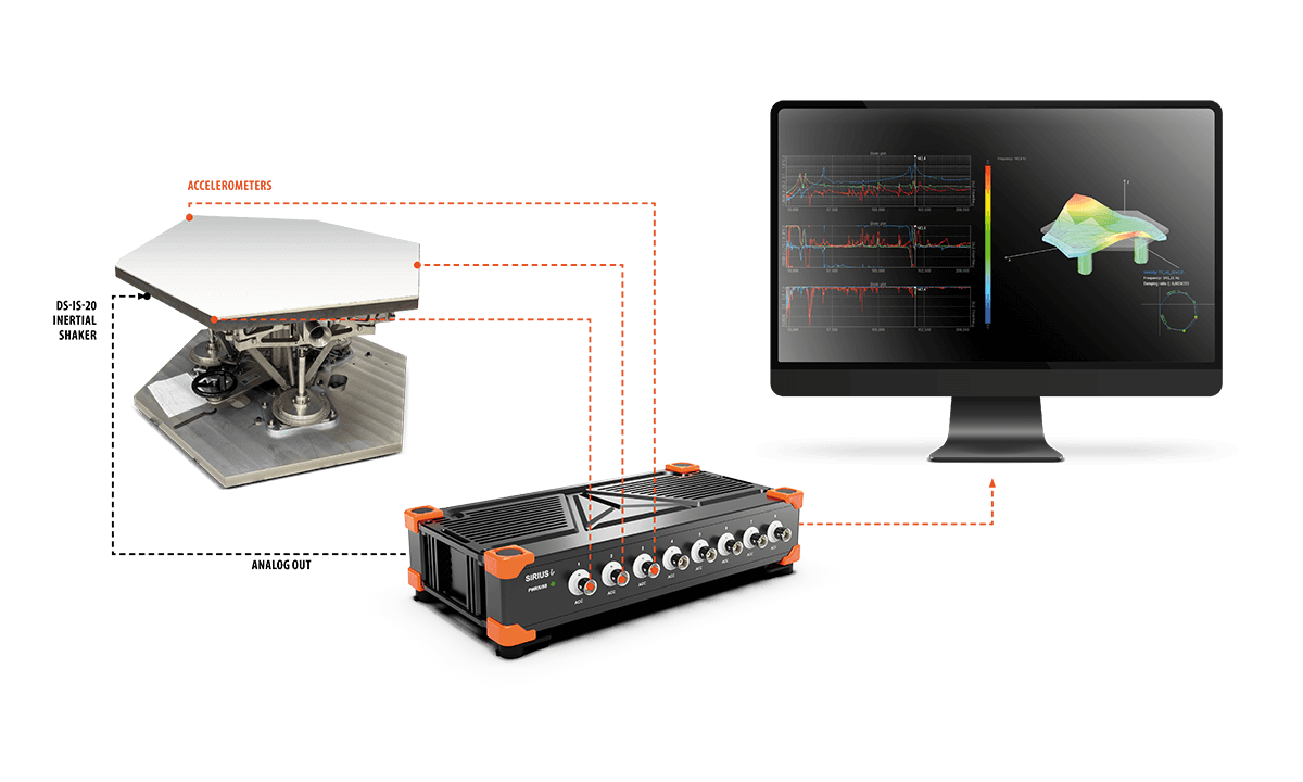
Figure 6. Setup for modal analysis of the mirror support structure.
Evaluation of Modal Analysis Test Setup
In the evaluation unit of the test setup, the vibrations are superimposed and evaluated regarding strength, phase, and coherence. In addition, the Dewesoft measuring system used calculates and visualises the mirror support as a 3D modal form. The representation on the display has been adapted to the typical requirements of this modal analysis. This means the quality and validity of the measurement can be very quickly recognised.
Therefore, the automated modal analysis enables a simple and at the same time efficient quality check of the mirror supports before assembly in the telescope. This provides a reliable control of thousands of installed complex components. Finally, this effort pays off quickly. By detecting hidden errors such as faulty screw connections or damaged parts early and reliably.
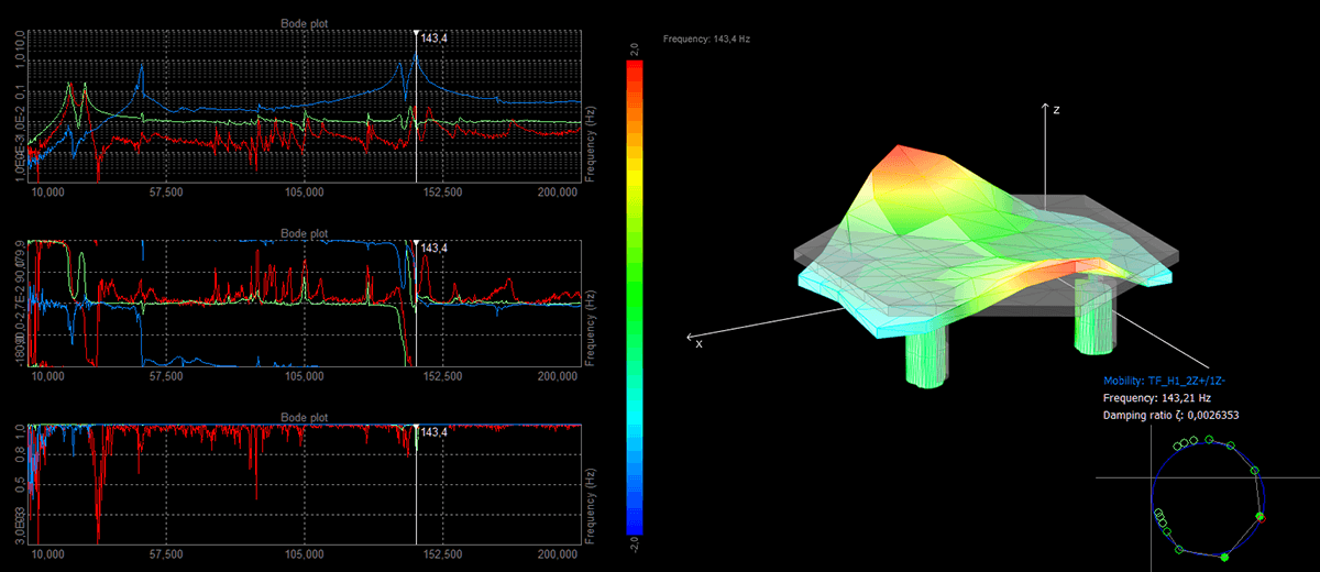
Figure 7. The strength, phase, and coherence of the vibrations of the kinematic mirror support are evaluated and displayed as a 3D modal form.
Conclusion – Space Telescope Vibration Measurements & Modal Analysis
In both vibration and modal analysis, the solutions from Dewesoft achieved a very good match between simulations and measurements. This was made possible by the theoretical considerations in advance. As well as the careful preparation of the test setups. Plus the high quality and accuracy of the measuring systems used.
Such metrological methods are not limited to the ELT. There are also a wide range of applications in other areas of research and development. In particular, the measurement of the introduced forces is of interest for applications in which sensitive system components are tested, regardless of their installation environment.
An example is the dimensioning and efficiency measurement of damping elements or fan mounts. With this type of modal analysis, a wide range of applications develop. This is because its use has become much more flexible. Thanks to new modal analysis software modules from Dewesoft.