This case study on High Voltage Testing of Railway Infrastructure was written by Konrad Schweiger, Sales Engineer at Dewsoft GmbH in Austria. To view the original article, click here. For more information on similar Dewesoft Systems, contact us.
Introduction
Firstly, HPA is a high voltage testing wagon. It is a mobile test unit for railway maintenance. It allows Austrian Company, ÖBB-Infrastruktur AG to check the operations and safety of the electrical infrastructure power on the railway at different points across Austria. The testing wagon needed modernisation of its measurement equipment. And Dewesoft delivered!
About ÖBB-Infrastruktur AG – The Customer
Firstly, ÖBB-Infrastruktur AG is part of the ÖBB-Holding AG, owned by the Republic of Austria. The company has approximately 18.700 employees. It is responsible for the planning, development, maintenance and operation of the entire ÖBB rail infrastructure. This includes train stations, routes, buildings, terminals, telecommunication systems and hydropower plants.
According to its corporate strategy paper, ÖBB-Infrastruktur AG must maintain the railway as the safest means of transport.
Innsbruck is the central control station. It performs the control, regulation and monitoring of the traction current supply. As well as the power plants and the 55/110 kV traction power grid. Power plants and frequency converters are centrally controlled. Therefore, depending on the load situation on the railway grid power is optimised using special software. The 15 kV traction current network is managed in two energy control centres.
Secondly, the traction power grid consists of generators, traction power lines, transformers and overhead contact lines. It is over 2000 km long. It operates at a frequency of 16.7 Hz. The grid distributes electricity from power stations and frequency converters to the substations. More than 60 substations transform the voltage from 55 or 110 kV of the traction current lines to 15 kV for the catenary to supply the railway.
Why conduct High Voltage Testing of Railway Infrastructure?
You may ask the above question. It is not only essential to prove the safety and reliability of any new and modified electrical system related to the railways. More importantly it is a tool to predict and prevent costly failures.
The main applications of the HPA are verification of the electrical safety of the grounding concept and high current component testing.
The HPA Testing Wagon
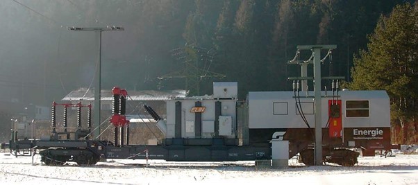
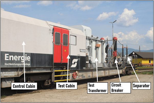
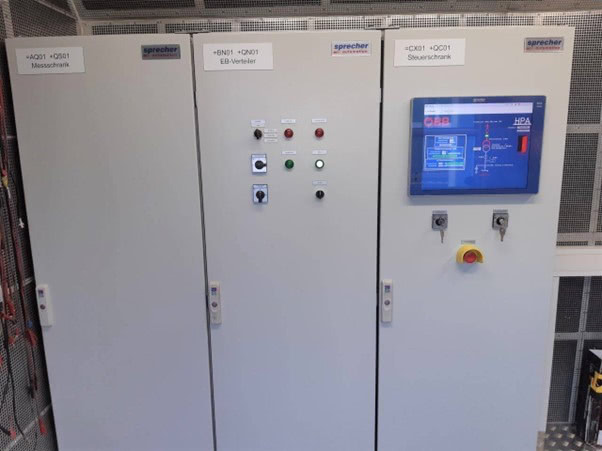
The ÖBB testing wagon – HPA (“Hochspannungsprüfanlage” – the high voltage test facility) is a rail vehicle based on a low loader wagon. The testing set up consists of a circuit breaker, power switch, testing transformer, an explosive proof test cabin and operator cabin. Highly skilled staff required for the job.
The HPA is over 20 years old. The current hardware and software were no longer valid and the old camera system did not provide usable videos and didn’t integrate with the software.
Therefore, modernisation of the entire measurement technology was necessary. Component testing had been outsourced. However, should again be carried out by ÖBB. Also, new processes had come into place. This required greater demands on the documentation of measurement and calibration.
Electrical Grounding Verification
Electrical systems of railways require proper grounding and bonding throughout the network. In addition to leaving wayside equipment susceptible to damage, the lack of appropriate grounding systems meant safety risks to rail workers and the general public.
Electrical energy needs to dissipate into a grounding system. Otherwise, it will stray into places it should appear. Therefore, potentially leading to human touch or step injuries. It could happen anywhere that exposed metal exists in the network that isn’t properly grounded or bonded. Stray current cause other hazards, especially in transit networks where the vehicle traction power is a high voltage electrical current.
Networks powered by a contact rail (or third rail) are susceptible to fires caused by electrical arcing incidents that spark combustion and light flammable debris.
Several components within the rail network that generally require grounding and bonding include:
- Running Rails
- Overhead Catenary and contact rails
- Wayside equipment such as interlockings, switch machines, intermediate signals
- Electrical/electronic enclosures throughout the network
- Communication towers and microwave installations
- Grade crossings
- Building and support facilities
- Onboard rolling stock
Verification Laws
ÖBB-Infrastruktur must verify the functionality of electrical grounding systems. Such testing is essential on all newly constructed or renovated overhead line and railway stations. As well as within operating sites, reinforced concrete structures, engineering structures and noise protection walls.
This verification follows the standard EN 50122-1:2017 Railway applications – Fixed installations – Electrical Safety, earthing and the return circuit – Part 1: Protective provisions against electric shock.
During Testing
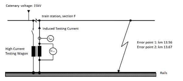
During this test, the conferring track segment is closed. It is electrically separated from the mains grid. Also the loop is closed at a defined position with grounding rods (Error point 1, Error point 2). The mobile transformer induces a constant test current with 16.7Hz into the catenary allowing touch potential. Eg. Between the rail and the earth can be measured. Other measurement points are: on the station’s floor, on metal fences close to the rails etc.
A 2.2 kOhm resistor stimulates the electrical resistance of a human body. The touch potential at different points along the infrastructure is measure as the test current is distributed over the various elements of the grounding structure. Then the sum is checked.
Furthermore, the testing team measure the voltage between the neutral (N) and earthing lines (PE – Protective Earth) on the AC sockets with the test current on and off. This enables analysis of the reverse traction current drag.
There are limit levels (and times) defined. Currents and voltages are measured continuously during the test. The outside weather station logs the actual weather conditions for documentation.
High Current Component Testing
High current test systems are applied to ensure the mechanical and thermal stability of equipment and components of the catenary system. This includes cables, generator stators, switching cells etc.
The test system heats the test object by inducing a current. Therefore, the test object is prepared to make a short circuit. In addition to the current, the high current test system measures the temperature of the test object at various points.
These tests validate the mechanical and thermal strength of the components of the railway line systems. The component tests are necessary. So that ÖBB can be sure that the heating during operation does not exceed impermissibly high values and that the required short circuit current is tolerated by all components in their systems.
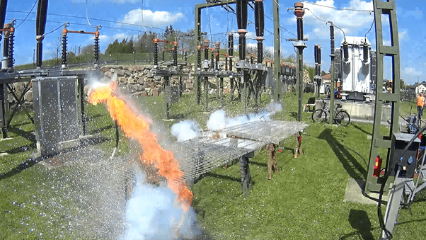
Since the transformer can provide high currents, the second important application is high current testing of railway infrastructure components. For example the shortcut test with 30 kA for 1 sec or the heating test with 1000 A for a few hours.
Grounding Sockets and Connector High Current Component Tests
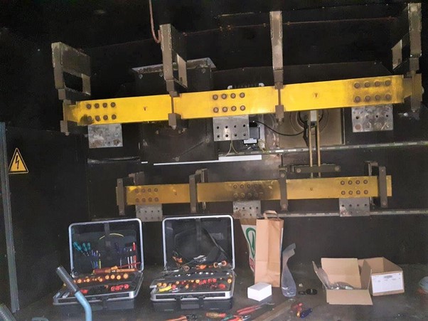
Components, such as grounding sockets and connectors, are taken out of the infrastructure. They are loaded with high-current to check their mechanical and electrical resilience. They must pass an initial long-term test – several hours – with a portable constant current source at the operating current. Then the temperature profile is logged.
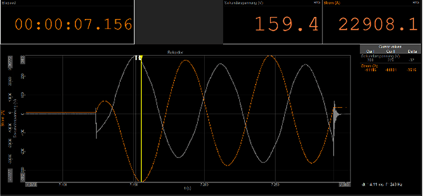
Then to test the components for short-circuit resistance. The test objects are connected to the test transformer and tested by exposure to a high-test current (30 kA) for about one second. The HPA logs the temperature, current, and voltage curves. It also makes video recordings of the test item during the test. Since all is synchronously measured, the high sampling rate is of concern.
Also, depending on weather conditions and the size of the object under testing, the testing team can perform their tests outside or inside the explosion-proof test cabin.
Therefore, these tests are essential to ensure the reliable and safe operation of all components in the railway infrastructure – and to reduce downtime. Punctual trains are a prerequisite for satisfied customers.
The Solution
Dewesoft supplied the solution that met the requirements for the modernisation of the ÖBB high-voltage test facility measurement technology:
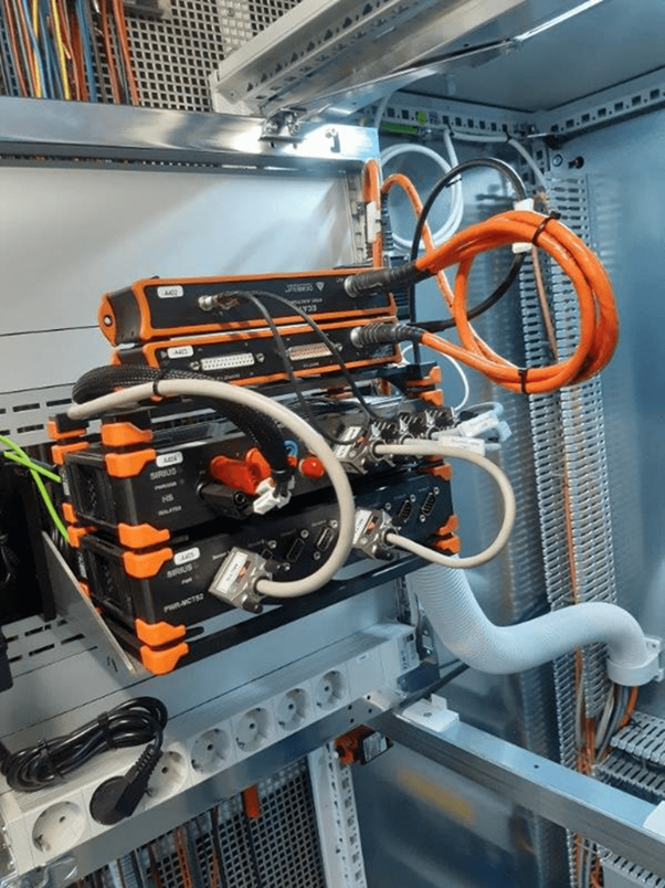
Hardware
- Firstly, the SIRIUS HS High-Speed DAQ system with various 1 MHz High- and Low-Voltage inputs
- MCTS2 unit for current transducer power supply
- KRYPTONi-8xDI-8xDO rugged IP67 EtherCAT DAQ module for digital in-/outputs
- As well as KRYPTONi-1xTH-HV high isolated temperature modules with the appropriate safety cables
- MCTS high precision current transducer (zero-flux principle)
- Rogowski coils for up to 30 kA
- Also a Temperature/humidity sensor for inside, by RS232 interface
- Vaisala Weather station WXT536 (wind speed & direction, rain amount, temperature, air pressure, relative humidity) for outside
- DS-CAM-600c synchronised Gigabit-Ethernet camera with onboard compression (optional: thermal camera)
- various mounting plates
Software
- DewesoftX Professional base version (lifetime free updates)
- Dewesoft SERIALCOM plugin: DewesoftX extension for communication with the RS232 temp/humidity-sensor
- Dewesoft NMEA-WS plugin: DewesoftX extension for communication with the Vaisala weather station
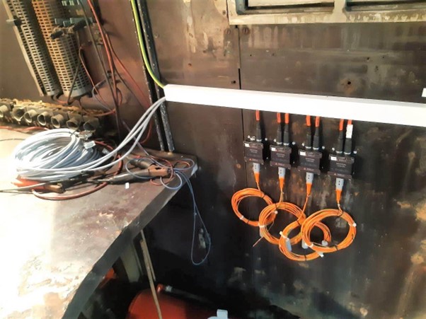
System Installation
At the time of system installation, the HPA team had parked the testing wagon inside a railway substation. Next to it, to the left and right, isolators of a few meters’ height were rising in the air. On the one hand, we from Dewesoft were a bit nervous – we didn’t know how to behave, where to walk, or which safety distances to keep. However, fascinated to see how it works.
Impressed by the testing team. The way it handled everything with routine. They mounted the few meters long shorting bars, operated the control system, etc. but always kept an eye on where everyone was at any time.
We enjoyed the pleasant company of the HPA team – these people were both professional and serious but also humorous. They worked somewhat like a team of mountain climbers. It seems working in dangerous environments brings people closer together.
Therefore, for testing purposes, the team loaded some pieces of metal with 30 kA. The aim was to see if signals were plausible and to optimise the viewing angle of the high-speed camera.
The testing team was even interested in measuring the time delay of the circuit switch. Since the control system can accurately switch on at, for example, the 90° phase point of the 16.7 Hz sine wave.
After installing the measurement system and placing the sensors in the test wagon, the testing team invited us to do some training on the Dewesoft Equipment.
Conclusion
ÖBB-Infrastruktur AG required that the DAQ system could be started manually. Either by an external digital input or, if the secondary current was present, involving a pre-trigger time. The Trigger options in the Storing section in DewesoftX realised this requirement.
The software allows multiple triggers on data, time, or even an FFT reference curve set in parallel. The trigger conditions ensure that high-speed data is only stored when the events occur. This functionality saves a lot of disk space.
Also, the synchronous acquisition of high-speed video and analog data like currents, voltages, HV-isolated temperatures, digital in-/outputs, and bus data like RS232 matched requirements. The intuitive user interface combined with the ability to analyse data without an additional software license makes daily work much easier for ÖBB-Infrastruktur AG.
In the end, the service company doing the measurements for ÖBB concludes: “The Dewesoft system fulfilled all requirements. And even more is included, functionality which we might use for future tasks. We are glad that the measurement system of this unique infrastructure testing wagon is now again state-of-the-art”.