Optimising ADC Gain in Data Acquisition — Why DualCoreADC® Matters
The Problem: Fixed Gain Limits Accuracy or Overloads the System
In many test applications, engineers must measure signals that occasionally sit below 5 V but can also spike toward 100 V. A standard Analog-to-Digital Converter (ADC) gain setting creates a trade-off:
- If the ADC range is set to 0–5 V, any signal exceeding that will clip and overload
- If the ADC range is set to 0–100 V, low-level signals will lose resolution and precision
Using multiple channels at different gains is inefficient — it increases hardware requirements and complicates analysis.
The Solution: Dewesoft DualCoreADC® Technology
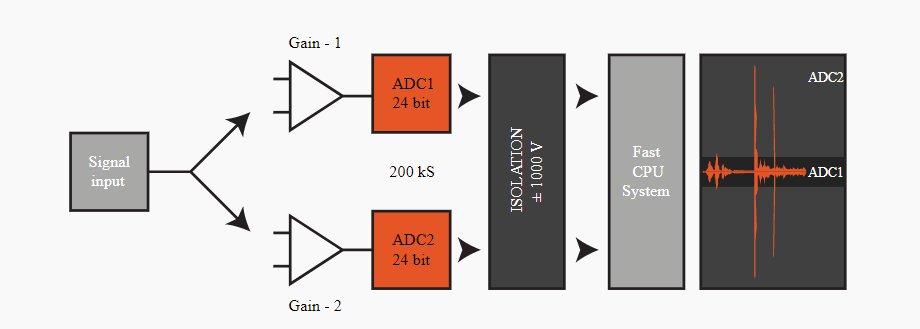
Dewesoft solves this limitation with DualCoreADC®, a patented technology that uses two independent 24-bit ADCs per channel. Each ADC measures the same input at different gain levels in real time and combines the data into a single seamless channel.
This design ensures:
- High voltage events are captured without overload
- Low-level signals are recorded with full resolution
- No manual switching or duplicate channels are required
- Compatible even with slow-changing signals such as thermocouples
Performance Advantages in Dewesoft SIRIUS DAQ Systems
With DualCoreADC®, Dewesoft SIRIUS DAQ platforms deliver exceptional measurement performance:
- >130 dB signal-to-noise ratio
- >160 dB dynamic range
- Up to 200 kS/s per channel
- Up to 20× less noise than typical 24-bit DAQ systems
This allows precise high-dynamic-range acquisition without sacrificing safety or resolution.
Need Hybrid Capability With Higher Sample Rates?
Some applications require both:
- Channels with ultra-high dynamic range and anti-aliasing, and
- Separate channels with much higher sampling speeds
Dewesoft addresses this with Hybrid ADC Technology, which combines the advantages of multiple converter architectures for mixed-signal applications. To understand this in more detail, explore Dewesoft’s overview of Hybrid ADC Technology.
Learn More
Metromatics supplies and supports Dewesoft DAQ systems and DewesoftX software across Australia and New Zealand.
For assistance in selecting the right DualCoreADC-based system for your application, contact Metromatics for technical support and local pricing.