This application note on Propeller Thrust Measurement in a VTOL Aircraft was originally provided by our friends at FUTEK.
In the application of Vertical Takeoff and Landing (VTOL) aircraft, including their electrical variants (eVTOL), propeller thrust measurement emerges as a critical factor for ensuring efficient design and operation. Unlike conventional helicopters, VTOL and eVTOL aircraft often use multiple propellers. Each propeller not only contributes to the total thrust needed for the aircraft’s vertical and horizontal movements. In addition it impacts the overall performance and stability.
The primary challenge for VTOLs is generating enough thrust. In order to counteract the aircraft’s weight and achieve lift-off and landing. Precise thrust measurements of each propeller are therefore vital to ascertain that the aircraft can perform safely and stably.
Moreover, understanding the torque produced by the propeller shaft is equally essential. This helps in optimising the combined operation of propellers and ensures their functioning within safe and efficient parameters.
Methods of Measuring Propeller Thrust
Thrust measurement in VTOLs is a process that involves understanding the force created by the rotation of the propeller blades. This force propels the aircraft forward through the generated airflow.
The typical approach involves using a load cell. Axially mounted to the motor stand base. This setup helps in measuring the upward lift load across various propeller speeds. The force exerted by the propeller in the axial direction (aligned with the propeller’s rotation axis) is quantified in Newtons (N).
Using Multi-Axis Load Cells for Enhanced Measurement
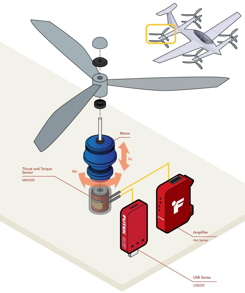
Bi-axis load cells play a significant role in simultaneously measuring the thrust and torque generated by a VTOL propeller. An example of such a device is the FUTEK MBA500 Thrust and Torque Sensor. It is a thrust measurement unit capable of capturing both axial forces and torques from the propeller.
The axial force represents the thrust (measured in Newtons), and the torque (measured in Newton-meters) is the force acting perpendicular to the rotation axis.
Operational Procedure for Thrust and Torque Measurement
- Mounting the Sensor: The bi-axial torque and thrust load cell, such as the MBA500, is mounted axially at the motor’s end. This sensor detects the motor’s reaction torque (Mz) without affecting its rotational performance.
- Running the Propeller: Following calibration, the eVTOL propeller is mounted on the thrust stand. Various RPMs are tested to measure the thrust and torque output. The MBA500’s Fz channel measures the propeller thrust, while the Mz channel gauges the motor’s back-torque, minimising mechanical crosstalk.
- Data Collection: This multi-axial setup, often combined with a USB225 device, allows for portable data collection. Engineers can use laptops to analyse live data in both outdoor and controlled indoor environments.
- Data Analysis: Post-testing, data from the bi-axial torque and thrust sensor is analysed using the IAA105 Digitally Configured Analog Voltage Amplifier. This analysis helps determine the propeller’s efficiency and power output, offering insights to optimize its design for specific applications.
This comprehensive approach to propeller thrust and torque measurement in VTOLs highlights the importance of precision in the aircraft’s operation, influencing both safety and performance.
Finally, for more information on this concept, contact us.
