Key Features & Benefits of the Multi-Axis Load Cell MTA600
Simultaneous 3-Axis Force Sensing — captures Fx, Fy, and Fz measurements in a single sensor, simplifying your system design.
High Capacities — rated for Fx and Fy at 2,500 lb each, and Fz at 5,000 lb.
Safe Overload Margin — 150 % of rated output on all axes to guard against transient loads.
Solid Accuracy & Repeatability
Nonlinearity ±0.5 % RO
Hysteresis ±0.5 % RO
Nonrepeatability ±0.2 % RO
Electrical Characteristics
Rated Output: ~1.50 mV/V (Fx, Fy) and ~0.75 mV/V (Fz)
Input / Bridge Resistance: 350 Ω for Fx, Fy; 700 Ω for Fz
Insulation Resistance ≥ 500 MΩ at 50 VDC
Mechanical & Dimensional Details
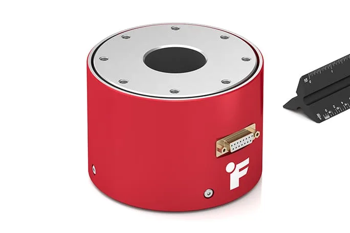
Flange-to-flange through hole design; inner diameter 1.72 in (≈ 43.7 mm)
Outer diameter 4.98 in (≈ 126.5 mm); height 3.5 in (≈ 88.9 mm)
Weight ~8 lb (≈ 3.6 kg)
Material: 17-4 PH stainless steel
IP Rating: IP40 (standard)
Temperature Range & Stability
Operating: 0 to 160 °F (≈ –17 to +71 °C)
Compensated: 60 to 160 °F (≈ 15 to 72 °C)
Temperature shift (zero/span): ±0.02 %/°F
Typical Applications of the Multi-Axis Load Cell MTA600
Wind tunnel models: lift, drag, side force measurement
Aircraft / flight control test benches
Triaxial dynamometer systems
Robotic actuator reaction and multi-axis load measurement
Multi-component force sensing in test rigs, structural systems, or aerospace research
Why Choose the Multi-Axis Load Cell MTA600
One sensor for three force axes — reduces footprint, cabling, and alignment errors.
Strong, reliable design — stainless steel construction, solid overload margins, designed for demanding environments.
Low crosstalk & well separated outputs — ensures that Fx, Fy, and Fz signals are distinct and usable.
Flange-to-flange design with through hole — allows structural elements to pass through, simplifying integration.
Support & calibration options — Metromatics can help with calibration, wiring, mounting, and application advice.
Ordering & Configuration Tips
If you would like more information about this product, please contact us.
When specifying an MTA600, consider:
Ensure the force ranges you need align with the 2500 / 2500 / 5000 lb specification.
Confirm mounting geometry and ensure your mechanical system can supply clean, aligned loads in all axes.
Plan connector / wiring layout (DB15 female connector by default) and ensure your instrument can support three axes.
Request 5-point compression calibration (standard) or optional tension/compression calibration if needed.
Account for temperature compensation, zero shift, and crosstalk effects in your system design.
Multi-Axis Load Cell MTA600 Models
| Item | Load Capacity | Mounting Type | Inner Diameter | Length | Height | Width | Outer Diameter |
|---|---|---|---|---|---|---|---|
| FSH04135 | 22241.1 N | Flange | 4.37 cm | 12.65 cm | 8.89 cm | 12.65 cm | 12.65 cm |
Finally, the MTA600 are a Multi-Axis Load Cell Series. Download the FUTEK MTA600 datasheet (PDF) to view technical specifications and configuration options.