What is Analog Signature Analysis?
Analog signature analysis (ASA) is a “power off” troubleshooting technique. Firstly, it applies a sinewave (AC) stimulus to a component creating a voltage vs. current signature. The signature displays on a computer monitor for analysis. This technique allows a trained technician to locate damaged and marginal components.
Four basic signatures – resistance, capacitance, inductance & semi conductance
All Analog Signature Analysis signatures are four basic components. These are resistance (any value from an open to a short), capacitance, inductance, and semi conductance. Understanding the basic signatures simplifies the analysis of composite signatures.
- Voltage is horizontal
- Current is vertical
An open circuit draws no current. Therefore, it is a horizontal line on the CRT. A short circuit draws maximum current. Therefore, it is a vertical line.
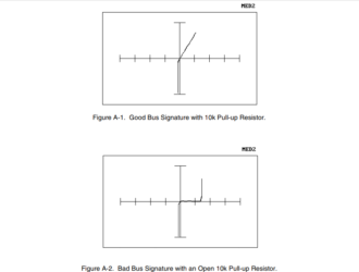
- Resistors have a constant voltage/current ratio causing a linear diagonal signature with the angle of slope being directly proportional to the resistance value.
- Capacitors and inductors cause a phase shift between voltage and current producing a circle or elliptical signature directly proportional to the amount of capacitance or inductance.
- Diodes, the simplest semi conductive device, allow current to flow in one direction and not the other. Signatures displayed by a horizontal line that goes vertical just after the centre axis of the display.
Complex or Composite Signatures
Complex or composite signatures are combinations of the four basic signatures. Integrated circuits are a various transistors. For example diodes, resistors, and capacitors. The signatures displayed by ICs are composites signatures. These devices have built-in protection circuits. Which allow current to flow in both directions displaying a signature that is vertical in the bottom half, then horizontal, then vertical in the top half. These signatures called “chair patterns”.
Common zener diodes will display a chair pattern that has a vertical break-over point at .6 volts (the conducting voltage of a silicon device) and a second break-over point at the rated voltage for the zener diode. Variations of this signature found in ICs are due to resistive and capacitive elements.
CMOS integrated circuits built with capacitors. Therefore, causing their signatures to display a loop in the “back” of the chair pattern. Leakage current is indicated by curvature of the linear portions. Also the rounding of corners in the diode or chair pattern.
Resistive (diagonal) portions of a signature not found in a good device indicate damage to the component. Capacitive signatures that flutter, vary in size, and change shape indicate a possible problem in the dielectric. Integrated circuits of the same type (e.g.7404) but differing in manufacturer can display slight differences because of the various ways in which the components are constructed. This is a normal condition and should not be confused with a device failure.
A clear solution
The multiple signature storage and merge features in the Huntron Workstation for Windows software can compensate for this by allowing the computer to store several serialised signature sets to compare against. Secondly, the degree of the failure must be related to the type of signature being sought. For example, a catastrophic PCB failure can be expected to be caused by a failed device with a dramatic signature difference from that of the same device in a known good PCB.
A marginally operating or intermittent board may have a failed component that indicates a small signature difference from a known good board. Internally shorted bipolar (TTL) ICs will produce a resistive signature. This will be a near straight line pivoting to the one o’clock position. A catastrophic short will exhibit this effect in the LOW range and results from a resistive value of four to ten ohms. Leakage current is the most common IC failure. It will increase a temperature increases.
Boards run at a higher temperature. Than at testing facilities. Therefore, a small leakage current can be a real problem. Leakage current shows up as a rounded transition (corner) or as a curvature in a normally straight line. There are parallel and loading effects on signatures of components that are in circuit. The lowest impedance device will tend to dominate that signature so analyse these
signatures carefully looking for tell-tale indications of the four basic signatures previously discussed.
This White Paper on Analog Signature Analysis was provided by our supplier Huntron. They are a manufacturer of tools for engineers and technicians who test, diagnose and troubleshoot printed circuit assemblies.
About Huntron
Huntron was founded in 1976 with the introduction of the Huntron Tracker, the pioneering troubleshooting tool that uses power-off signature analysis to identify component failures on printed circuit boards. Over time, Huntron has added robotic automation. This is to help deal with the increase in board complexity and help users save valuable time. The current Access Prober product line can decrease test times tenfold when compared to manual methods.
Metromatics has proudly been Huntron’s exclusive distributor in Australia and New Zealand for over 29 years.
For more information on the Huntron Product Line, contact us
