
An autonomous mobile robot may know exactly where it is—but does it know whether its payload is safe to carry?
Autonomous Mobile Robots (AMRs) and Automated Guided Vehicles (AGVs) increasingly move materials through warehouses, factories, hospitals, laboratories and other industrial environments. Their navigation and obstacle-detection systems help them travel through these facilities. However, safe and reliable material handling also depends on what is happening on the robot itself.
An overloaded platform may place excessive demand on its drive system and structure. A payload positioned too far to one side can affect stability, handling and component wear. By integrating load cells beneath the payload platform, designers can give an AMR or AGV real-time information about both the total load and how that load is distributed.
This measurement data can help the vehicle identify an unsafe payload condition before movement begins or support an appropriate response while it is operating.
What is the difference between an AMR and an AGV?
Although the terms are used interchangeably, AMRs and AGVs generally operate differently.
An Automated Guided Vehicle usually follows a defined route using infrastructure or guidance methods such as magnetic tape, wires, reflectors or other markers. It suits repetitive material-handling tasks where routes remain relatively consistent.
An Autonomous Mobile Robot uses onboard sensors, mapping and control software to understand its surroundings and select or adjust its route. This allows it to work in environments where people, equipment and material flows may change.
Both types of vehicle can carry loads that vary in weight, position and shape. Therefore, both may benefit from integrated payload measurement.
Why does payload monitoring matter?
An AMR or AGV may be designed for a particular maximum payload, but the onboard controller cannot confirm the actual weight simply from the programmed task. The vehicle could receive an overloaded pallet, an incorrectly positioned container or an item whose weight differs from the expected value.
Without direct measurement, the system may not identify the condition until it affects acceleration, braking, steering, battery consumption or stability.
Load monitoring can provide two important types of information.
Total load verification
Load cells can measure the forces transferred through the vehicle’s payload supports. Adding the individual measurements provides the total supported load.
The controller can compare this result with the vehicle’s allowable operating range before authorising movement. Depending on the system design, an overload condition could trigger an operator alert, prevent the vehicle from starting or initiate another programmed response.
This feedback may also support process checks. For example, a vehicle could confirm that a container has been loaded, verify that the expected material was collected or identify a major difference between the expected and measured payload.
Uneven load and centre-of-gravity monitoring
Total weight alone does not show where the payload is positioned. A load may remain below the vehicle’s maximum capacity while still being concentrated too far towards one edge or corner.
When load cells measure vertical force at multiple known points, the controller can compare those measurements to evaluate weight distribution. If one support carries substantially more force than the others, the payload may be off-centre.
Using the measured forces and the known position of each sensor, the control system can estimate the payload’s centre of gravity under suitable static or controlled conditions. This information can help identify loading conditions that could reduce stability, increase structural stress or place uneven demand on the drive system.
The response remains the responsibility of the vehicle’s control and safety architecture. For example, the system will request that the load be repositioned, prevent travel, restrict speed or bring the vehicle to a controlled stop.
How a three-point load measurement system works
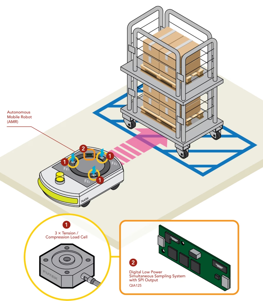
FUTEK presents a conceptual AMR and AGV load-monitoring arrangement using three tension and compression load cells installed between the mobile platform and its load-carrying surface.
Each load cell measures vertical force at a separate support point:
- Fz1 at the first mounting position
- Fz2 at the second mounting position
- Fz3 at the third mounting position
Together, these measurements allow the onboard system to determine the combined load and compare the force supported at each position. A three-point arrangement can also avoid the mechanical ambiguity that may occur when four supports do not share a load evenly because of tolerances, platform deflection or an uneven mounting surface.
The correct mechanical arrangement still depends on the size and structure of the platform, the expected payload, load direction, stiffness and operating environment. Designers must ensure that forces transfer through the sensors as intended and that side loads, bending moments and mounting effects do not introduce unacceptable measurement errors.
Measuring the load with the FUTEK QLA428
In FUTEK’s example, three QLA428 square-flange diaphragm load cells measure the forces acting beneath the payload platform.
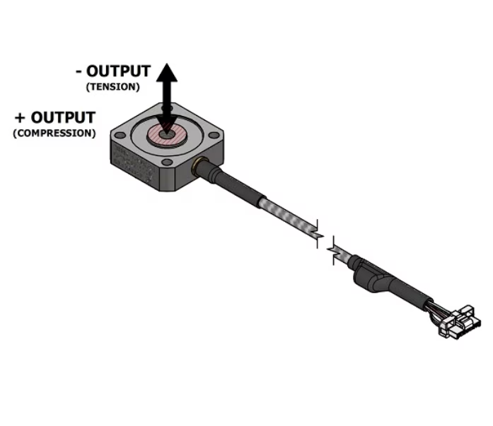
The QLA428 is a tension and compression load cell with a low-profile, square-flange form. This style can be useful where a sensor must be incorporated into a compact mechanical assembly and measure force along its intended axis.
For an AMR or AGV application, the load-cell capacity should not be selected by dividing the maximum payload by three and choosing the nearest range. Engineers also need to consider:
- The weight of the platform and fixtures supported by the sensors
- Unequal load distribution
- Acceleration, braking and cornering forces
- Shock and vibration
- Loading and unloading impact
- Expected overloads
- Required measurement resolution
- Mechanical mounting and available space
- Environmental temperature and exposure
The highest-loaded sensor can experience considerably more than one-third of the total load when the payload is positioned away from the platform centre. An appropriate engineering margin and overload capacity are therefore important.
Converting three load-cell signals for the onboard controller
Strain-gauge load cells typically produce a small analogue output expressed in millivolts per volt. This signal must be excited, conditioned and converted before the robot’s processor can use it.
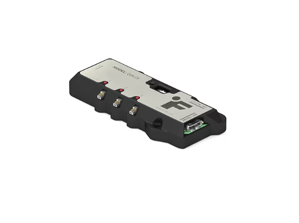
FUTEK’s conceptual system pairs the three load cells with the QIA125 low-power, three-channel digital signal conditioner. It can interface with three load cells simultaneously and convert their analogue signals into digital measurement data for the AMR or AGV controller.
According to FUTEK, the QIA125 supports SPI and UART communications, provides sampling rates up to 4,800 samples per second and offers up to 18.1 bits of noise-free resolution. Its multi-channel architecture and low-power design make it relevant to embedded, battery-powered measurement applications where space, energy consumption and communication speed matter.
Using one conditioner for the three measurement points can simplify integration and give the controller coordinated access to each force channel.
How can an AMR or AGV use the measurement data?
Payload data can support more than a single overload alarm. Depending on the vehicle design and control software, it may be used to:
- Verify that the payload falls within allowable limits
- Confirm that an item has been loaded or removed
- Detect a substantially off-centre payload
- Alert an operator before movement begins
- Prevent travel until the load is corrected
- Select operating limits appropriate to the measured payload
- Record payload history for operational analysis
- Identify unexpected changes while transporting material
- Support load-transfer and process-verification tasks
Load measurement does not replace navigation, collision-avoidance or functional-safety systems. Instead, it adds another source of real-world feedback that designers can incorporate into the vehicle’s broader control and risk-management strategy.
Static and dynamic measurement considerations
An AMR is not always stationary when measurements are taken. Acceleration, braking, cornering, floor transitions and vibration can temporarily change the force measured at each support point. These dynamic forces may look like a change in payload weight or position if the system does not account for them.
The required approach depends on the application. It may include:
- Taking a stable measurement before the vehicle moves
- Applying digital filtering
- Using different thresholds for stationary and moving conditions
- Allowing for acceleration and braking in the control logic
- Calibrating the complete assembled platform
- Testing with representative payload positions and operating manoeuvres
Where centre-of-gravity estimation is required. The algorithm, mechanical geometry and calibration procedure must be developed and validated for the actual platform. Applications involving personnel, medical use or safety-critical loads may also require additional independent protective measures and compliance assessment.
AMR and AGV load monitoring where is it used?
Integrated load measurement may benefit mobile robotic systems used in:
- Warehousing and distribution: transporting pallets, cartons, totes and order-picking racks
- Manufacturing: moving parts, tooling, workpieces and assemblies between processes
- Automotive production: supplying components to production and assembly areas
- Hospitals and healthcare facilities: transporting linen, supplies, meals, waste or equipment
- Laboratories and pharmaceutical facilities: moving samples, materials and controlled loads
- Mining and resources: carrying tools, samples, parts or monitoring equipment
- Aerospace and Defence: transporting components or integrating load feedback into unmanned ground platforms
- Robotics research: developing and validating mobile manipulation and material-handling systems
The same measurement principles can be applied for robotic carts, mobile manipulators and other self-propelled platforms that must verify what they are carrying.
Selecting a load-monitoring solution for an AMR or AGV
The most suitable load cell and signal-conditioning arrangement depends on the complete mechanical and electrical design. Before selecting components, engineers should define:
- Minimum, nominal and maximum payload
- Payload dimensions and possible positions
- Number and location of load-bearing supports
- Available space and mounting method
- Static, shock, vibration and dynamic loads
- Accuracy and resolution required
- Measurement speed
- Supply-voltage and power-consumption limits
- Required output or communications interface
- Operating temperature and environmental exposure
- Prototype and anticipated production quantities
Custom sensor geometry, environmental requirements or output configurations need to be considered for production AMR and AGV designs.
Discuss your AMR or AGV payload measurement requirements
Finally, Metromatics supplies FUTEK load cells, force sensors and instrumentation to customers throughout Australia and New Zealand. We can assist engineers, equipment manufacturers, system integrators and research teams with selecting suitable sensing and signal-conditioning components for an AMR, AGV or mobile robotic platform.
To discuss an application, provide the expected payload range, platform dimensions, load-support arrangement, operating environment and preferred controller interface. This information will help identify an appropriate measurement approach for further engineering evaluation.
Contact Metromatics to discuss load monitoring for your autonomous mobile robot or automated guided vehicle.