
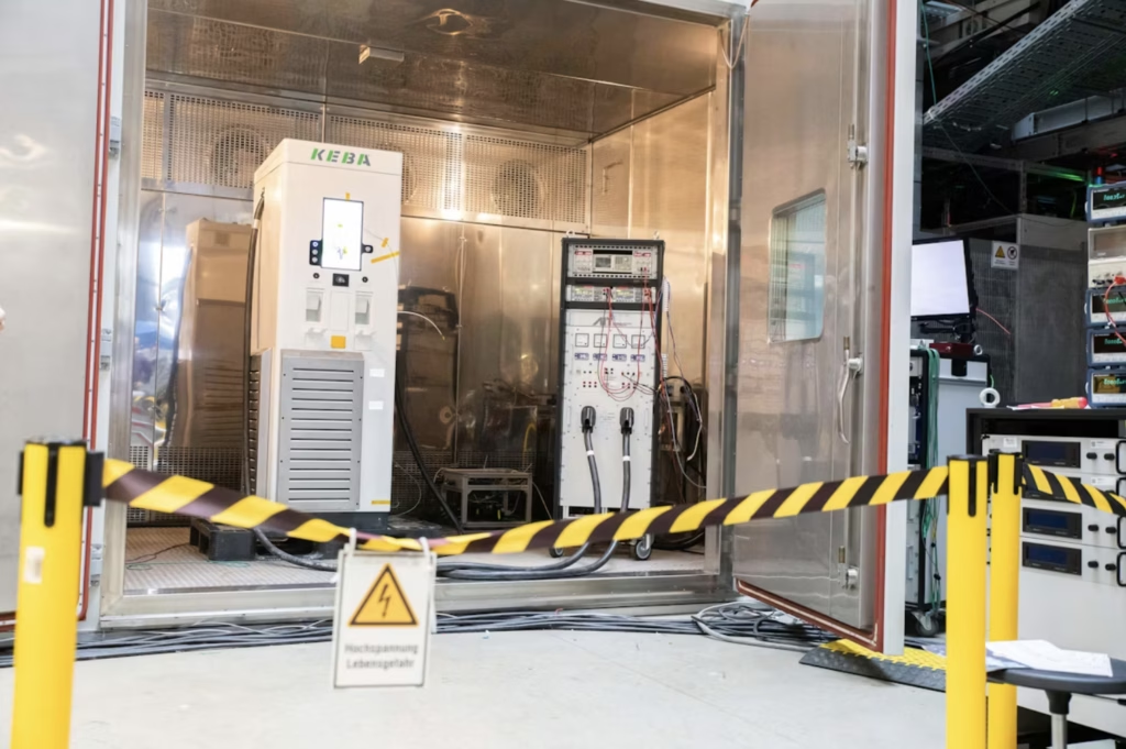
In Dewesoft’s account of a climate-chamber test, KEBA evaluated its 320 kW KeContact DCA10 charger at AIT’s SmartEST laboratory in Austria. The question was how charging behaved as temperature increased, and whether power recovered after cooling.
Measuring the Response
AIT’s regenerative EV emulator supplied the load. The team measured three-phase AC input and DC output together using a SIRIUSi-XHS-4xHV-4xLV power analyser with zero-flux current transducers. An IOLITE R8 system collected temperature measurements, including the chamber and touch display. Analysis used DewesoftX with its Power Analyzer module.
The Documented Result
According to Dewesoft’s case study, the charger progressively reduced its output as temperatures increased, while maintaining stable charging. As conditions cooled, charging power increased automatically.
This behaviour was central to KEBA’s evaluation. The team needed to check that the charger’s temperature control response worked as intended: reducing power under thermal stress and recovering as temperatures fell. The reported results demonstrated that response under the conditions tested.
Recording AC input and DC output together also allowed the engineers to examine conversion losses alongside charging behaviour. Dewesoft describes the output power as only slightly below the input, although it does not provide a numerical efficiency figure.
For engineers planning similar tests, the practical lesson is to examine the complete temperature cycle. Checking how power reduces, whether charging continues and how output recovers provides more useful evidence than a maximum-power reading alone.
Building a Measurement Brief
The current SIRIUS XHS power-analyser specification describes a system for three phase AC and single phase DC measurement. Its selectable acquisition modes serve different measurement needs, including high-speed transient capture. Raw-data storage also supports later analysis.
When considering a system for a proposed test, consider which events must be resolved and which quantities need to be compared. Ask for the voltage inputs, current sensors, acquisition settings and analysis configuration to be specified together. This is more useful than selecting a system based solely on the highest available sampling rate.
The IOLITE R8 provides eight slots for measurement modules. Select those modules against the required temperature sensors and other signals; an empty chassis is not a complete temperature-measurement system.
Relevance for Australian and New Zealand Projects
For a local charger evaluation, ask for evidence at the conditions relevant to the proposed installation. Define the operating temperatures, load profile and acceptable behaviour before testing. Include what should happen when output is limited and when normal conditions return.
Those requirements give the test team a basis for judging the measurements. They also help a purchaser distinguish a charger’s rated output from the performance evidence needed for a particular site. This Austrian project is an example of an evaluation approach, not certification for an Australian or New Zealand installation.
Contact Metromatics to discuss the electrical and temperature measurements required for your charger test. Share the voltage and current ranges, signals to record and events you need to investigate so that a suitable Dewesoft configuration can be discussed.