
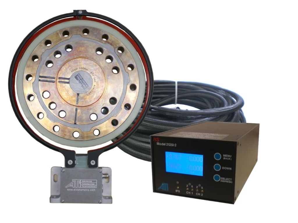
Small torque fluctuations inside a gearbox, electric motor or driveline can create noticeable noise and vibration. Yet engineers often struggle to measure these events because the component may simultaneously transmit thousands of newton metres of torque.
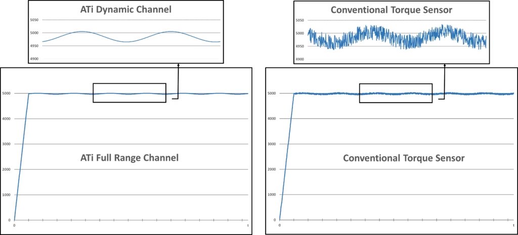
A conventional torque sensor may accurately show the overall load while hiding the much smaller torque variations that cause gear whine, rattle and other noise, vibration and harshness (NVH) problems.
ATi’s high-speed torque and torsional-vibration measurement solutions address this challenge by combining dual-range sensing, high-speed digital RF telemetry and non-contact induction power. As a result, engineers can measure the main operating torque while also capturing fast, low-level torsional events within the rotating component.
Why Are Gear-Mesh Torque Fluctuations Difficult to Measure?
As gear teeth engage, they create small and rapid changes in transmitted torque. These variations can reveal gear-mesh behaviour, electric-motor harmonics, gear-reducer characteristics and other sources of unwanted noise or vibration.
However, these events are often tiny compared with the component’s total operating torque.
For example, a sensor may need to measure a steady 5,000 Nm load while identifying dynamic variations below 20 Nm. If the sensor noise floor sits close to, or above, the signal of interest, the useful information disappears into the measurement noise.
Simply increasing the gain does not solve this problem. It amplifies sensor noise as well as the torque fluctuations engineers want to investigate.
Two Measurement Channels for Two Different Signals
ATi’s Dual Range Dynamic Torque Sensing option uses two independent strain-gauge bridges and measurement channels.
The full-range channel uses DC coupling to measure the total torque applied to the component. It captures the main operating load, including steady and slowly changing torque.
Meanwhile, the independently ranged AC-coupled dynamic channel focuses on smaller, faster torque fluctuations associated with gear mesh and other NVH events. It ignores the static torque level.
Depending on the selected configuration, the dynamic channel can measure a range as low as 1% of the primary channel.
For example, a 5,000 Nm system can include a second channel configured for a 50 Nm dynamic range. Consequently, engineers can examine low-level torsional activity in detail without losing visibility of the component’s full operating torque.
What Does the 2.4 GHz Technology Do?
The 2.4 GHz specification refers to the digital radio link that transfers data from the rotating sensor to the stationary receiver.
It does not describe the frequency of the torsional vibration being measured.
Instead, the 2.4 GHz telemetry solution provides the data-transfer capacity needed for higher sample rates and wider analogue measurement bandwidth. The high-speed dynamic channel can provide:
- Up to 77,000 samples per second
- Measurement bandwidth from approximately 5 Hz to 19 kHz
- Real-time data transmission from the rotating sensor
- Digital error checking during data transfer
A higher sample rate captures rapidly changing torque events in greater detail. At the same time, the wider bandwidth lets engineers investigate higher-frequency torsional behaviour that slower systems may filter out or miss entirely.
These capabilities matter particularly when testing high-speed electric motors, gear reducers, automotive axles and other rotating components with high-frequency NVH signatures.
Measure Static and Dynamic Torque Simultaneously
One of the system’s key advantages is its ability to measure dynamic torque while the component carries its normal operating load.
During an end-of-line axle test, for example, the full-range channel can measure the torque transmitted through the axle. At the same time, the dynamic channel can reveal the smaller torque fluctuations created by gear engagement.
This approach helps engineers investigate:
- Gear whine and rattle
- Gear-mesh irregularities
- Electric-motor torque ripple
- Gear-reducer behaviour
- Driveline resonance
- Transient torsional events
- Component-to-component variation
- Assembly or manufacturing defects
As a result, engineers can assess how a component performs under realistic operating conditions rather than relying only on unloaded or simplified test data.
Torque and Torsional Vibration: Related but Different Measurements
Torque measurement identifies the twisting force transmitted through a shaft or component. Torsional vibration, by contrast, describes rapid changes in rotational speed or angular acceleration around the shaft’s normal rotation.
A shaft can rotate continuously in one direction while still speeding up and slowing down slightly during each revolution. Combustion events, gear engagement, electric-motor harmonics and load changes can all create these angular fluctuations.
ATi also offers accelerometer-based torsional-acceleration measurement. Engineers can use this alongside torque measurement to gain a broader view of NVH behaviour.
Together, these measurements show both the force transmitted through the component and the resulting rotational vibration.
Non-Contact Power and Data Transfer
Rotating-component testing creates another practical challenge: engineers must supply power and transfer data without restricting movement or influencing the measurement.
ATi uses digital RF telemetry to send measurement data from the rotating sensor to the stationary receiver. Induction power supplies continuous power to the rotating electronics without batteries, slip rings or a direct electrical connection.
This non-contact approach delivers several practical benefits:
- No slip-ring wear or electrical noise
- No bearings within the torque-sensor assembly
- Continuous operation without battery replacement
- Lower maintenance requirements
- Greater tolerance of shaft movement and run-out
- Less sensitivity to dust and oil than optical transmission systems
- Minimal alignment requirements between rotating and stationary components
Therefore, the system suits demanding test environments where vibration, contamination and high rotational speeds can affect conventional torque-transducer arrangements.
Sensor Formats for Different Test Installations
ATi high-speed torque sensing systems are available in several mechanical configurations, including disk-style, dual-flange and flange-mounted sensor designs.
Where a standard inline torque transducer will not fit, ATi can also develop a custom sensor or instrument an existing shaft or component.
The most suitable configuration depends on:
- Maximum static and dynamic torque
- Required measurement bandwidth
- Expected torsional frequencies
- Rotational speed
- Shaft or flange dimensions
- Available installation space
- Permissible mechanical modifications
- Environmental conditions
- Required analogue output and DAQ compatibility
- Continuous or short-duration test requirements
Where Can High-Speed Torque Measurement Be Used?
High-speed torque measurement can support a wide range of rotating-machinery applications, including:
- Automotive axle and transmission testing
- Electric-motor and gear-reducer development
- EV powertrain NVH analysis
- End-of-line quality testing
- Internal-combustion-engine driveline development
- Heavy-equipment drivetrain testing
- Aerospace propulsion and rotating-component testing
- Marine propulsion systems
- Defence-vehicle development
- Industrial gearbox testing
- Research and university laboratories
The technology delivers the greatest value when engineers need to separate small, fast dynamic torque variations from a much larger operating load.
Is a High-Speed System Required for Every Torque Test?
Not every torque measurement requires 77,000 samples per second or 19 kHz bandwidth.
A standard torque sensor may be entirely suitable for steady torque, gradual load changes or lower-frequency events. However, engineers should consider a high-speed system when the signal of interest is small, changes rapidly or sits close to the noise floor of the existing sensor.
Before selecting a system, identify:
- The maximum torque to be measured
- The smallest torque fluctuation of interest
- The expected frequency range
- The required sample rate
- Whether static and dynamic torque must be measured simultaneously
- Whether torsional acceleration is also required
- The available mounting arrangement
- The output required by the data acquisition system
Discuss Your Torque and Torsional-Vibration Application
ATi high-speed torque measurement systems help engineers capture torsional events that conventional torque sensors may miss.
Metromatics supplies and supports ATi rotating telemetry and wireless torque measurement systems throughout Australia and New Zealand. We can help you assess the expected torque range, shaft speed, measurement bandwidth, sensor format and data-acquisition requirements.
Contact Metromatics to discuss high-speed torque measurement, torsional-vibration analysis or a customised rotating telemetry solution for your application.