A Practical Guide for Maintenance and Repair Teams
When a printed circuit board fails, the first question many technicians ask is, “Where are the schematics?”
Unfortunately, in many industrial environments, the answer is often the same: unavailable.
Whether maintaining legacy manufacturing equipment, maintenance teams frequently encounter printed circuit boards (PCBs) with limited documentation. In addition, obsolete components, and little support from the original manufacturer.
Traditional troubleshooting methods can be time-consuming and risky,. Particularly when powering up a faulty board may cause additional damage. Fortunately, modern diagnostic techniques allow technicians to troubleshoot electronic circuit boards without schematics. Therefore, helping organisations reduce downtime, improve repair success rates, and extend the life of critical equipment.
Why Circuit Board Troubleshooting Is Challenging Without Documentation
Electronic systems have become increasingly complex over the past decade. Modern PCBs often contain densely packed mixed-signal circuitry, programmable devices, power electronics, and custom components.
When documentation is unavailable, technicians face several challenges:
- Unknown circuit functionality
- Limited access to replacement boards
- Difficulty identifying faulty components
- Increased troubleshooting time
- Greater risk of damaging components during testing
- Expensive “repair versus replace” decisions
These challenges are particularly common when working with legacy equipment where manufacturer support has ended or spare parts are difficult to source.
The Limitations of Traditional Fault-Finding Methods
Most maintenance teams rely on tools such as:
- Digital multimeters
- Oscilloscopes
- LCR meters
- Functional power-on testing
While these instruments remain valuable, they often require an understanding of how the circuit is designed to operate.
In many situations, technicians may not know:
- Expected voltage levels
- Signal waveforms
- Component relationships
- Normal operating conditions
Powering on a faulty board can also introduce additional risks, including short circuits, component damage, or further system failures.
This is where power-off diagnostic techniques can provide a significant advantage.
What Is Analog Signature Analysis?
Analog Signature Analysis (ASA) is a non-destructive, power-off testing method used to identify faults on electronic circuit boards.
Rather than powering the board and measuring live signals, ASA injects a small AC stimulus into the circuit and measures the electrical response.
The resulting signature provides a visual representation of the circuit’s electrical characteristics.
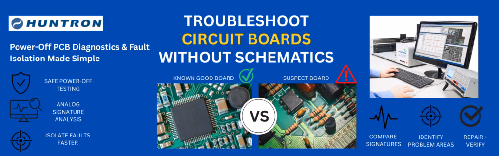
By comparing signatures from a suspect board against a known-good reference board, technicians can quickly identify abnormalities and isolate potential faults.
Because the board remains unpowered during testing, ASA can safely evaluate circuits without risking additional damage to sensitive electronics.
How to Troubleshoot Circuit Boards Without Schematics
Step 1: Obtain a Known-Good Reference Board
One of the most effective troubleshooting approaches is comparison testing.
A working board becomes the baseline against which all measurements are compared.
This allows technicians to identify differences between:
- Functional components
- Suspect components
- Intermittent faults
- Degraded devices
Comparison-based diagnostics often reveal issues that may not be obvious using conventional testing methods.
Step 2: Perform Power-Off Analysis
With the board removed from service, power-off testing can begin.
This approach offers several benefits:
- No risk of powering a faulty board
- Safe testing of sensitive electronics
- Faster fault isolation
- Ability to test damaged or non-functional assemblies
Power-off diagnostics are particularly useful for industrial control systems, power electronics, embedded computers, and specialised electronic equipment.
Step 3: Compare Electrical Signatures
Using Analog Signature Analysis, technicians compare measurements from the suspect board against the known-good board.
Differences in the signature patterns may indicate:
- Shorted components
- Open circuits
- Leaking semiconductors
- Damaged capacitors
- Faulty integrated circuits
- Intermittent or marginal failures
This comparison method narrows the search area significantly, allowing technicians to focus on the most likely fault locations.
Step 4: Isolate the Fault Region
Instead of troubleshooting the entire PCB, ASA helps identify the specific section of the board not performing normally.
By progressively comparing signatures across different areas of the board, technicians can quickly narrow the investigation to a smaller group of components.
This targeted approach reduces troubleshooting time and improves repair efficiency.
Step 5: Verify and Repair
Once the fault region has been identified, traditional tools such as multimeters, oscilloscopes, and component testers can be used to verify the diagnosis.
This combination of power-off diagnostics and conventional test equipment provides a highly effective workflow for repairing complex electronic assemblies.
Common Applications for Schematic-Free PCB Troubleshooting
Power-off diagnostic techniques are widely used across numerous industries, including:
Industrial Automation
- PLC control systems
- Motion control electronics
- Machine automation equipment
- Process control systems
Mining and Resources
- Motor drives
- Control panels
- Monitoring systems
- Power conversion equipment
Rail and Transportation
- Passenger information systems
- Signalling electronics
- Communications systems
- Vehicle control equipment
Defence and Aerospace
- Mission computers
- Radar electronics
- Communications systems
- Data acquisition equipment
Medical Devices
- Imaging systems
- Diagnostic equipment
- Laboratory instruments
- Monitoring systems
Semiconductor Manufacturing
Semiconductor fabrication facilities rely on highly specialised electronic systems for process control, temperature regulation, motion control, and automation. When failures occur, maintenance teams require rapid fault isolation to minimise production downtime. So they can make informed repair-versus-replace decisions.
Benefits of Troubleshooting Without Schematics
Organisations that implement power-off diagnostic techniques can achieve several benefits:
Reduced Downtime
Faster fault isolation helps return equipment to service more quickly.
Improved Repair Success Rates
Technicians can identify component-level faults even when documentation is unavailable.
Lower Maintenance Costs
Accurate diagnostics support better repair-versus-replace decisions and reduce unnecessary board replacements.
Extended Equipment Life
Legacy systems can remain operational long after manufacturer support has ended.
Improved Maintenance Consistency
Repeatable testing procedures reduce dependence on individual technician experience.
How Huntron Simplifies Circuit Board Troubleshooting
Huntron’s range of power-off diagnostic tools combines Analog Signature Analysis, automated probing systems, and advanced test management software to simplify PCB troubleshooting.
Solutions such as the Huntron Tracker 3200S, Access Prober systems, and Huntron Workstation software enable maintenance teams to:
- Compare suspect boards against known-good references
- Detect component-level faults
- Automate testing procedures
- Reduce troubleshooting time
- Improve repair consistency
- Support predictive and preventative maintenance strategies
These capabilities make Huntron particularly valuable when working with complex electronics, legacy systems, and equipment where schematics are unavailable.
Conclusion
Finally, Troubleshooting printed circuit boards without schematics no longer has to be a frustrating and time-consuming process.
By combining power-off diagnostics, Analog Signature Analysis, and comparison testing against known-good boards, maintenance teams can safely identify faults, reduce downtime, and make more informed repair decisions.
For organisations responsible for maintaining critical industrial, defence, rail, medical, and manufacturing equipment, schematic-free diagnostics provide a practical path to improving reliability while extending the life of valuable electronic assets.
If your maintenance team regularly encounters complex circuit boards with limited documentation? Power-off diagnostic solutions from Huntron may provide a faster and more effective approach to fault isolation and repair.
Need Assistance with Huntron Diagnostic Solutions?
Metromatics is the authorised distributor for Huntron products in Australia and New Zealand. Providing local sales, technical support, product selection assistance, training, and after-sales service.
Contact our team to discuss PCB diagnostics, fault isolation, power-off testing, and automated troubleshooting solutions for your maintenance and repair applications.